Methods for applying energy to tissue using isolated energy sources

a tissue and energy source technology, applied in the field of tissue energy application methods, can solve the problems of skin sagging, wrinkles, and other undesirable distortions, and achieve the effect of preventing energy from affecting the outer layer of skin and improving appearan

Inactive Publication Date: 2010-08-26
SYNERON MEDICAL LTD
View PDF101 Cites 24 Cited by
  • Summary
  • Abstract
  • Description
  • Claims
  • Application Information

AI Technical Summary

Benefits of technology

[0015]The invention provides improved systems and methods of percutaneously delivering energy to tissue where the systems and methods enable a physician (or other medical practitioner) to precisely control the areas or region of tissue that receives energy. In one aspect of the invention, the methods and systems produce cosmetically beneficial effects of using energy to shrink collagen tissue in the dermis in an effective manner that prevents the energy from affecting the outer layer of skin. However, the devices and method described herein can target the underlying layer of adipose tissue or fat for lipolysis or the breakdown of fat cells. Selecting probes having sufficient length to reach the subcutaneous fat layer allows for such probes to apply energy in the subcutaneous fat layer. Application of the energy can break down the fat cells in that layer allowing the body to absorb the resulting free fatty acids into the blood stream. Such a process can allow for contouring of the body surface for improved appearance. Naturally, such an approach can be used in the reduction of cellulite. In addition, the systems and methods are also useful for treating other skin surface imperfections and blemishes by application of a percutaneous treatment.

Problems solved by technology

Exposure of the skin to environmental forces can, over time, cause the skin to sag, wrinkle, form lines, or develop other undesirable distortions.
These and other effects of the normal aging process can present an aesthetically unpleasing cosmetic appearance.
Still, laser or chemical resurfacing leads to prolonged redness of the skin, infection risk, increased or decreased pigmentation, and scarring.
In one example, fabrication of an electrode array may cause undesired cross-current paths forming between adjacent electrodes resulting in an increase in the amount of energy applied to tissue.
In such systems that treat in a non-invasive manner, generation of energy to produce a result at the dermis results in unwanted energy passing to the epidermis.
Accordingly, excessive energy production creates the risk of unwanted collateral damage to the skin.

Method used


Image

  • Methods for applying energy to tissue using  isolated energy sources
  • Methods for applying energy to tissue using  isolated energy sources
  • Methods for applying energy to tissue using  isolated energy sources

Examples


example

Model of the Bipolar RF System

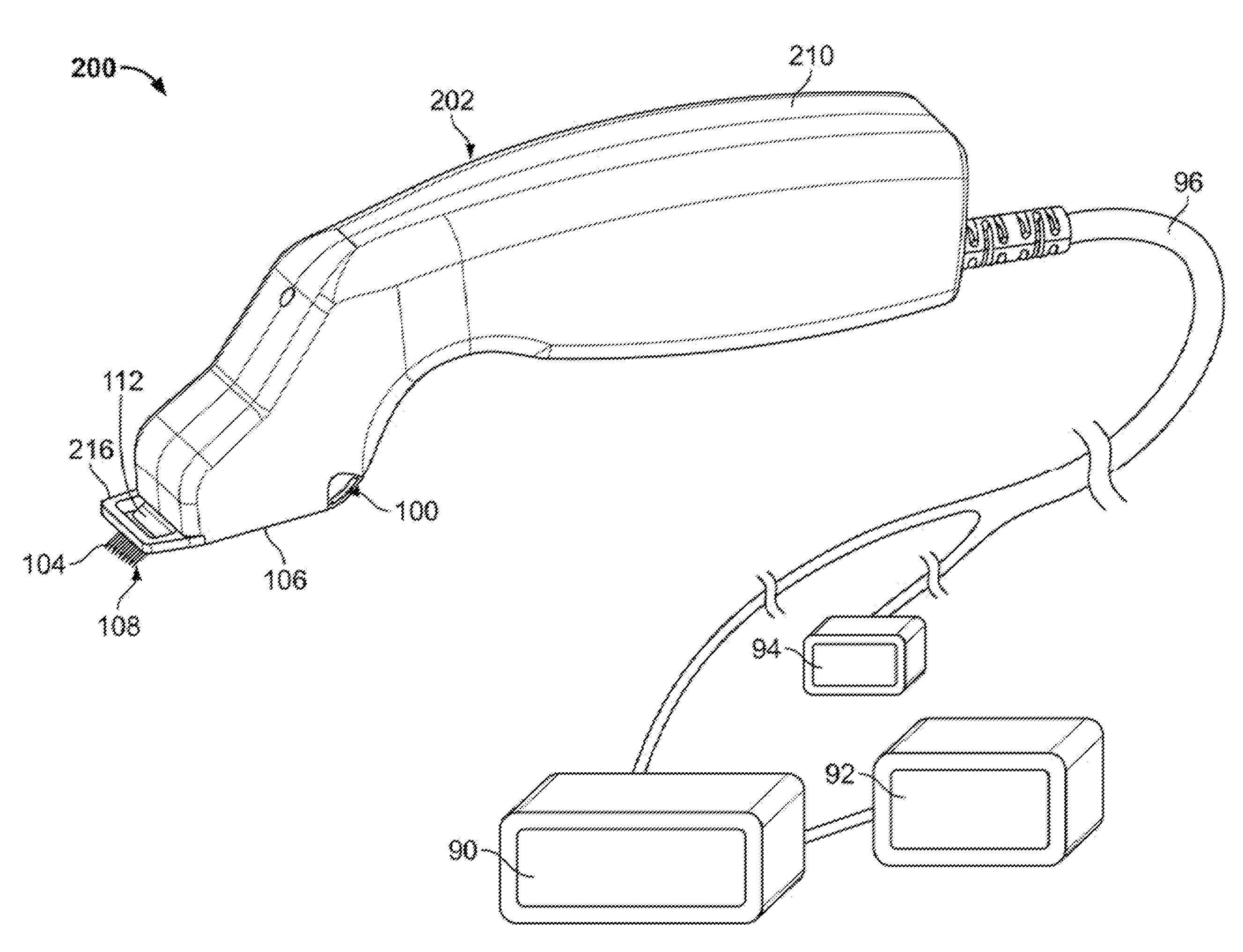
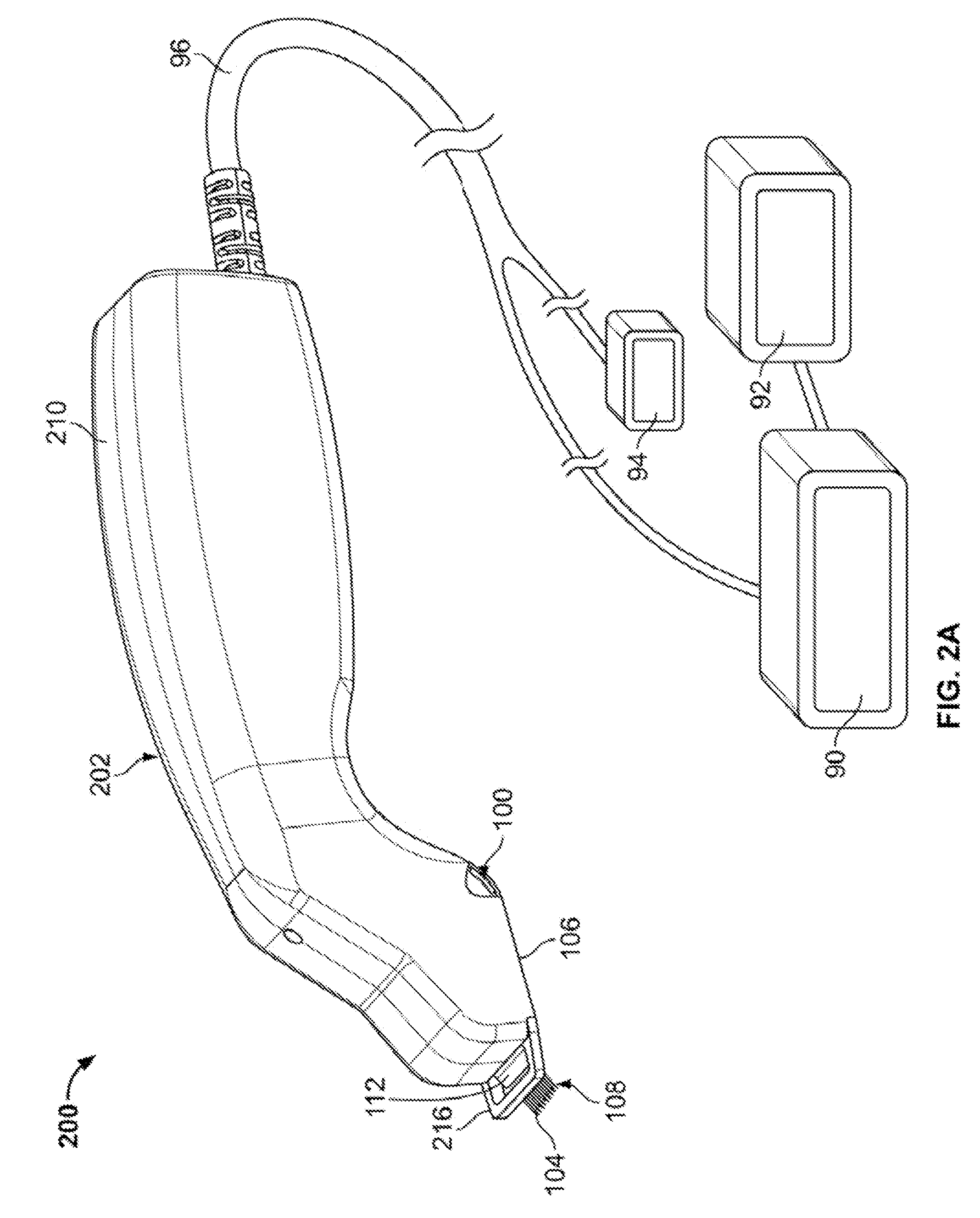
[0212]A variation of the bipolar system described above was modeled using finite element analysis to characterize the dynamics of energy deposition and thermal profile patterns. The actual system comprised a 5-pair 30 gauge microneedle array in combination with thermoelectric cooling to protect the epidermis during RF application (as discussed above). The proximal end of each microneedle is insulated with a biocompatible material, leaving the distal 3 mm exposed to form the electrode in tissue. A thermocouple embedded in the tip of each electrode pair measures tissue temperature during treatment to provide real-time feedback to the generator via a proportional integration derivative (PID) control algorithm. The treating physician can select the desired target temperature and pulse duration as clinical endpoints.

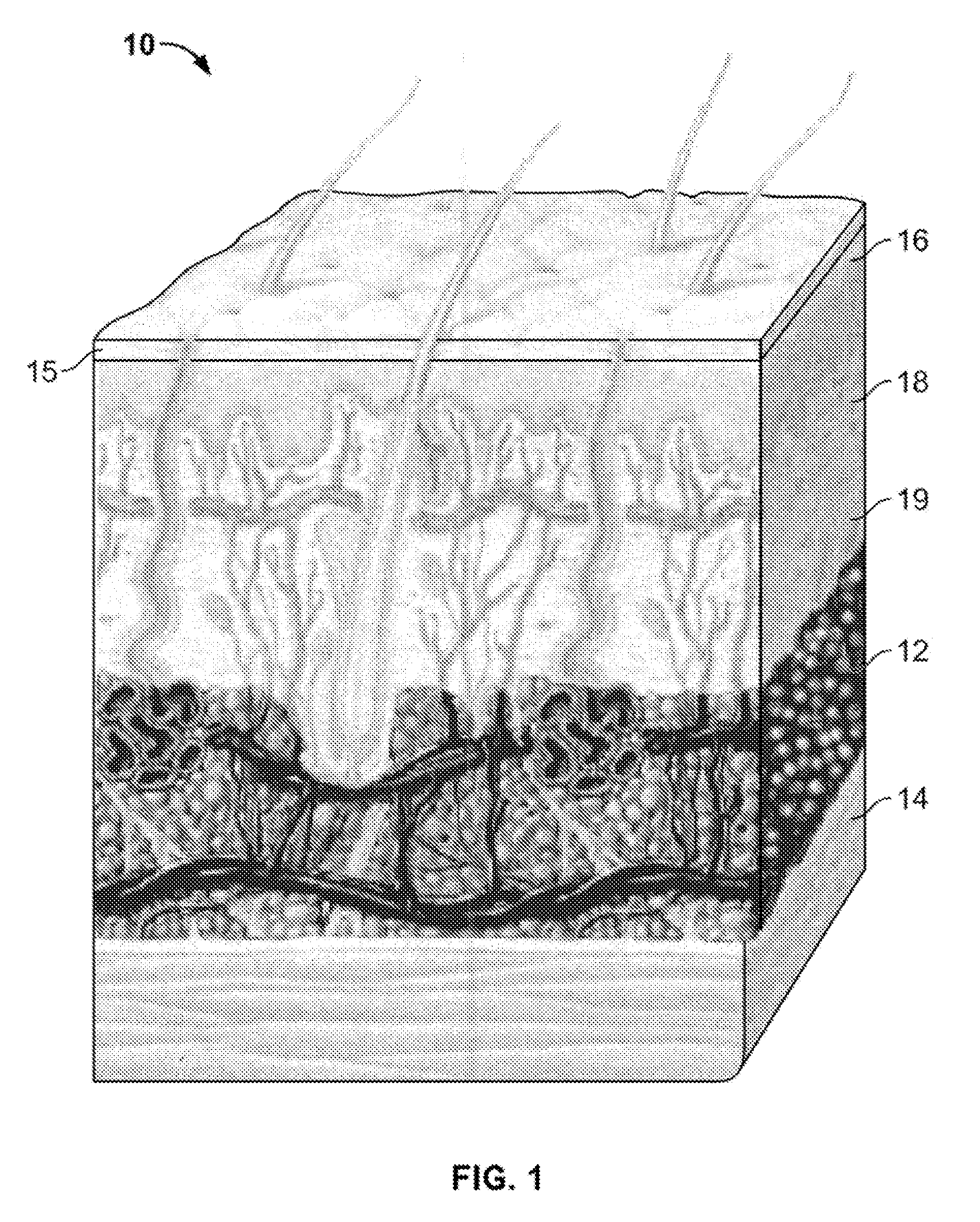
[0213]The model consisted of a single electrode pair of the above 5-pair system modeled with Comsol Multiphysics software (Comsol, Burlington, M...


PUM


Abstract

The invention provides a system and method for percutaneous energy delivery in an effective, manner using one or more probes. Additional variations of the system include array of probes configured to minimize the energy required to produce the desired effect.

Description

CROSS-REFERENCE[0001]This application is a continuation of U.S. patent application Ser. No. 12 / 392,936 filed on Feb. 25,2009 entitled DEVICES AND METHODS FOR PERCUTANEOUS ENERGY DELIVERY, the entirety of which is incorporated by reference.BACKGROUND OF THE INVENTION[0002]The systems and method discussed herein treat tissue in the human body. In a particular variation, systems and methods described below treat cosmetic conditions affecting the skin of various body parts, including face, neck, and other areas traditionally prone to wrinkling, lines, sagging and other distortions of the skin.[0003]Exposure of the skin to environmental forces can, over time, cause the skin to sag, wrinkle, form lines, or develop other undesirable distortions. Even normal contraction of facial and neck muscles, e.g. by frowning or squinting, can also over time form furrows or bands in the face and neck region. These and other effects of the normal aging process can present an aesthetically unpleasing cos...

Claims


Application Information

Patent Timeline
Patent Type & Authority Applications(United States)
IPC IPC(8): A61B18/14A61B18/18
CPCA61B18/18A61B18/1815A61B2018/0047A61B2018/00452A61B2018/00458A61B18/203A61B18/14A61B2018/00464A61B2018/143A61B2018/1869A61B2018/00011A61B2018/126A61B2090/3937A61B2018/0016A61B2018/00791A61B2018/1253A61B2018/00779A61B2090/395A61B2018/00023A61B18/1477A61N7/00A61B2018/00047A61N2007/0047A61B2018/00875A61B2018/00005
Inventor MEHTA, BANKIM H.
Owner SYNERON MEDICAL LTD
Why Eureka
Try Eureka