Devices and Methods For Controlling Patient Temperature

a technology for controlling patient temperature and devices, applied in the field of devices and methods for controlling patient temperature, can solve the problems of low interest in clinical use of mild therapeutic hypothermia, lack of concrete guidelines for cooling patients, and low enthusiasm for the use of therapeutic hypothermia

Active Publication Date: 2010-08-26
ADVANCED COOLING THERAPY INC
View PDF31 Cites 31 Cited by
  • Summary
  • Abstract
  • Description
  • Claims
  • Application Information

AI Technical Summary

Benefits of technology

[0035]At least one aspect of the present technology provides one or more methods for inducing systemic hypothermia. The methods comprise inserting a heat transfer device, including a fluid path defined by an inflow lumen and an outflow lumen, into a patient's esophagus; initiating flow of a cooling medium along the fluid path; and circulating the medium along the fluid path for a time sufficient to induce systemic hypothermia in the patient. The heat transfer device may include a discrete heat transfer region that is confined to the patient's esophagus. The patient may be maintained in a state of hypothermia for at least about two hours, for example. The methods may further comprise monitoring at least one physiological parameter of the patient, such as body temperature. The methods may further comprise maintaining the patient's body temperature below about 34° C.

Problems solved by technology

However, because of the numerous complications of moderate-to-deep hypothermia and the difficulty in inducing these temperature reductions, enthusiasm for the use of therapeutic hypothermia waned.
However, the AHA therapeutic hypothermia guidelines lack a concrete description of exactly how to cool patients.
Despite widespread support for mild therapeutic hypothermia in the context of cardiac arrest, including consensus recommendations from major resuscitative organizations, the use of mild therapeutic hypothermia in clinical practice remains low.
Many clinicians report that therapeutic hypothermia is too technically difficult to achieve in practice.
In addition, health care professionals occasionally need to induce hypothermia during certain surgical procedures or prevent inadvertent hypothermia and the multiple adverse effects that result from uncontrolled and unintended deviations from normal body temperature.
Although inadvertent operative hypothermia is considered one of the most preventable surgical complications, existing methods to control body temperature are limited in efficacy, such that the incidence of inadvertent operative hypothermia for surgical patients can exceed 50%.
Surface cooling is limited by the rate at which cooling can occur, due to the tendency of blood flow to be shunted away from skin and towards the core.
External devices, such as vests or blankets, significantly limit access to important patient areas that are often needed in critical care, such as for catheter placement, and require removal or modification to perform CPR.
Surface cooling techniques such as ice packs limit the precision with which a patient's temperature can be controlled.
Cooling with ice packs and conventional cooling blankets often results in unintentional overcooling.
Several issues exist with these current methods: (1) excessively warm room temperature creates an uncomfortable environment for the surgical team, (2) forced-air warmers are bulky and may impact the surgical field; they tend to be inefficient and must be used for extended periods of time in the operating room, and (3) none of these systems adequately control or manage temperature, leading to both overheating or, more often, inadequate warming.
Invasive temperature management treatments often require significant personnel involvement and attention to perform successfully.
Moreover, certain invasive temperature management modalities have been associated with overcooling, overheating, or, more often, inadequate warming.
The use of intravenous fluid as a temperature management modality has the undesirable effect of contributing to circulating fluid volume overload, and has been found to be insufficient for maintaining target temperature.
In addition, several temperature-controlling modalities, particularly those that employ inflatable balloons, limit access of the health care provider to particular anatomical structures that may be crucial for patient care, such as the stomach.
To date, no available modality for controlling patient temperature has been found that sufficiently overcomes the technical, logistical, and financial barriers that exist.

Method used


Image

  • Devices and Methods For Controlling Patient Temperature
  • Devices and Methods For Controlling Patient Temperature
  • Devices and Methods For Controlling Patient Temperature

Examples


example 1

Cooling of a Model System

[0139]An experiment was conducted to quantify the approximate rate of temperature reduction achievable by use of an exemplary embodiment of the present technology. Target temperature reduction is 4° C. Data were collected and plotted on a common X-Y graph, as shown in FIG. 7.

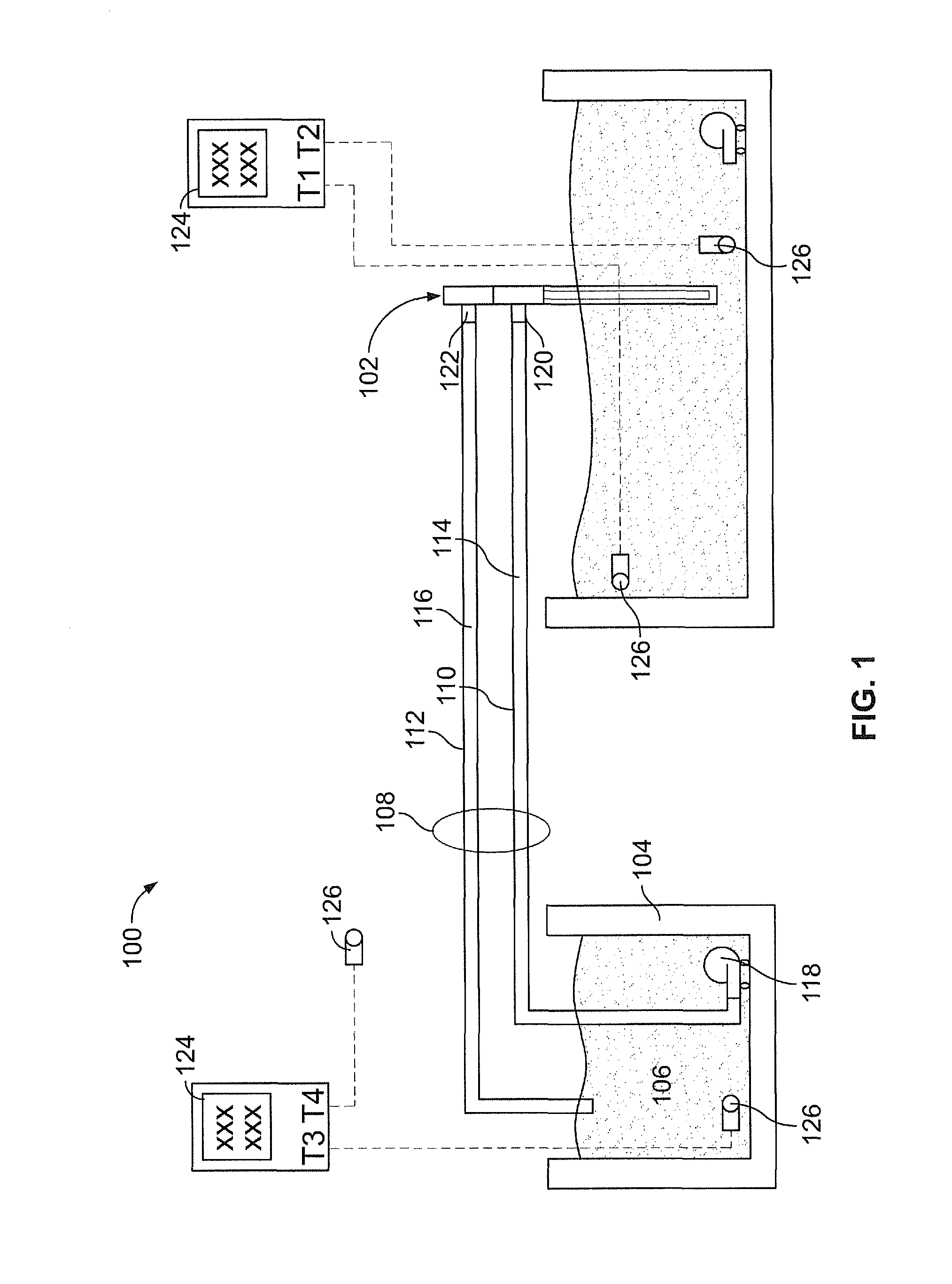
[0140]The arrangement of equipment for this experiment is shown in FIG. 1. A brief description of each piece of equipment is as follows:[0141]1. The heat transfer device 102 was an exemplary embodiment of a heat transfer device according to the present technology[0142]2. An insulated container, 96 cm (l)×36 cm (w)×36 cm (h), containing 88 kg water at the initial temperature shown in Table 1 represented the mass to be cooled.[0143]3. A 110V electric pump, Little Giant Model PES-70 (4.4 L / min free-flow) was used to circulate hot water within the insulated container (2) to maintain homogeneous temperature of water within this container.[0144]4. The heat exchanger 104 comprised an insulated ...

example 2

Operative Temperature Management

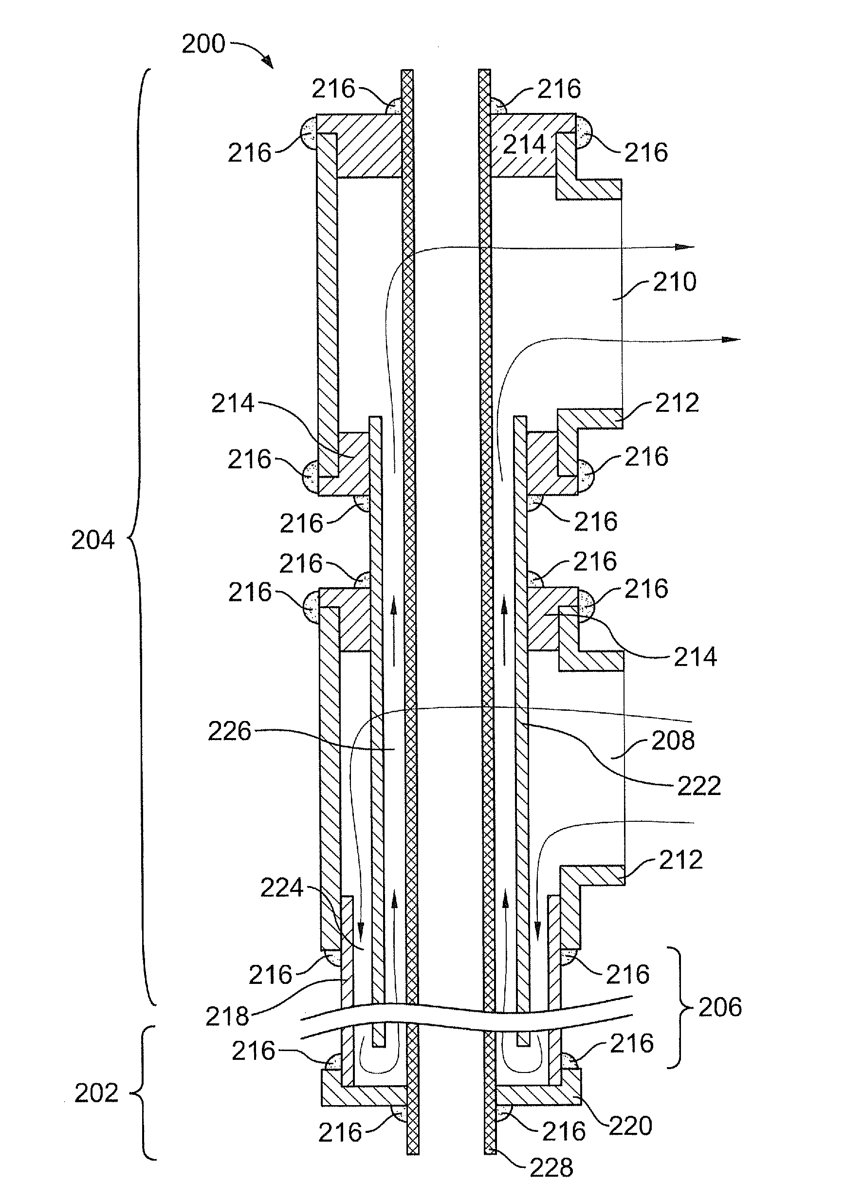
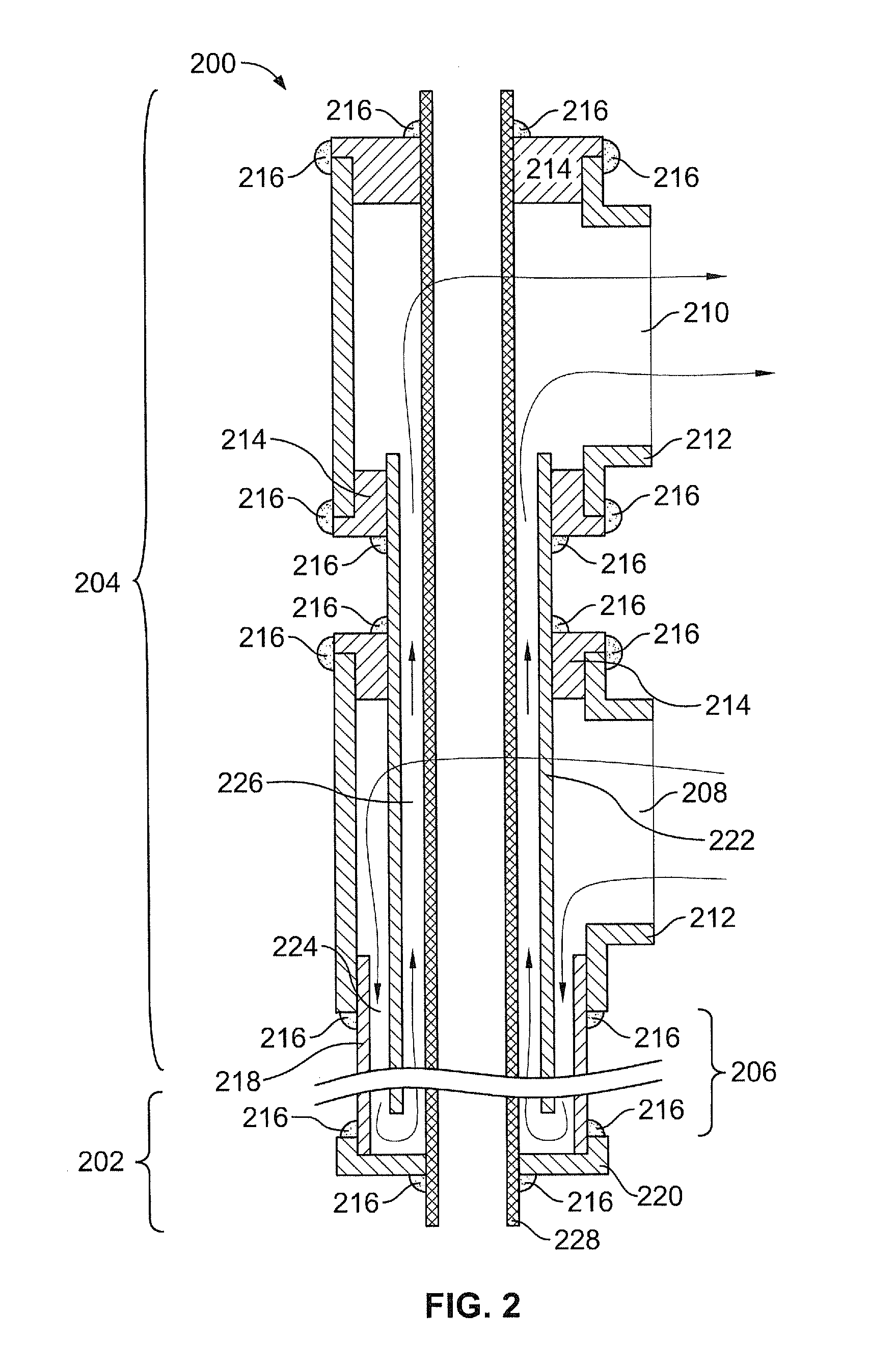
[0164]A heat transfer device according to the present technology was utilized in an animal study as described below. The heat transfer region of the heat transfer device was approximately 70 centimeters in length (to accommodate the length of the snout) and had a diameter of about 1.4 centimeters, for a surface area of about 305 cm2.

[0165]A large swine with a mass of 70 kg was chosen to best represent the size and average mass of a human patient. The swine was singly housed in an Association for the Assessment and Accreditation of Laboratory Animal Care, International (AAALAC) accredited facility, with primary enclosures as specified in the USDA Animal Welfare Act (9 CFR Parts 1, 2 and 3) and as described in the Guide for the Care and Use of Laboratory Animals (National Academy Press, Washington D.C., 1996).

[0166]The swine was anesthetized with a pre-anesthetic mix of Telozole / Xylazine, then provided with anesthesia via inhalational route with isoflur...

specific embodiments

[0187]The devices, methods, and systems described herein can be illustrated by the following embodiments enumerated in the numbered paragraphs that follow:

[0188]1. A method for inducing systemic hypothermia comprising:

[0189]inserting a heat transfer device into an esophagus of a patient, wherein said heat transfer device includes a fluid path defined by an inflow lumen and an outflow lumen;

[0190]initiating flow of a cooling medium along said fluid path; and

[0191]circulating said medium along said fluid path for a time sufficient to induce systemic hypothermia in said patient.

[0192]2. The method of paragraph 1, wherein said heat transfer device includes a discrete heat transfer region and said heat transfer region is confined to said esophagus.

[0193]3. The method of paragraph 1, further comprising cooling said medium to a temperature below normothermia.

[0194]4. The method of paragraph 1, further comprising maintaining said patient in a state of hypothermia for at least two hours.

[019...


PUM


Abstract

Relatively non-invasive devices and methods for heating or cooling a patient's body are disclosed. Devices and methods for treating ischemic conditions by inducing therapeutic hypothermia are disclosed. Devices and methods for inducing therapeutic hypothermia through esophageal cooling are disclosed. Devices and methods for operative temperature management are disclosed.

Description

RELATED APPLICATIONS[0001]This application claims the priority of U.S. provisional application Ser. No. 61 / 155,876, filed Feb. 26, 2009, which is incorporated by reference in its entirety.FEDERALLY SPONSORED RESEARCH OR DEVELOPMENT[0002][Not Applicable]MICROFICHE / COPYRIGHT REFERENCE[0003][Not Applicable]BACKGROUND OF THE INVENTION[0004]In industrial countries, 36 to 128 per 100,000 inhabitants per year experience a sudden out-of-hospital cardiac arrest (“OHCA”) with survival remaining a rare event. Cardiovascular disease affects an estimated 80,700,000 North American adults, with approximately 2400 individuals dying from cardiovascular disease daily (an average of one death every 37 seconds). Approximately 310,000 coronary heart disease deaths due to OHCA occur annually.[0005]According to data reported by the National Registry of Cardiopulmonary Resuscitation in 2007, over 75% of patients having cardiopulmonary arrest events did not survive the event. For those who did survive the e...

Claims


Application Information

Patent Timeline
Patent Type & Authority Applications(United States)
IPC IPC(8): A61F7/12
CPCA61B2017/00084A61F2007/126A61F7/12B33Y80/00
Inventor KULSTAD, ERIKCAHERTY, HUGH PATRICK
Owner ADVANCED COOLING THERAPY INC
Why Eureka
Try Eureka