Hollow fiber membrane for treating liquids

a hollow fiber membrane and liquid treatment technology, applied in the direction of membranes, filtration separation, separation processes, etc., can solve the problems of high disposal cost of the large amount of diatomaceous earth required, inability to incinerate used diatomaceous earth, and insufficient etc., to suppress the formation of cake layers, excellent filtration stability, and adequate flexibility of the inner surface

Active Publication Date: 2010-09-02
TOYO TOYOBO CO LTD
View PDF11 Cites 18 Cited by
  • Summary
  • Abstract
  • Description
  • Claims
  • Application Information

AI Technical Summary

Benefits of technology

[0024]With its adequate flexibility of the inner surface, a characteristic of the hollow fiber membrane of the present invention is that it significantly suppresses formation of a cake layer when used for filtration of a liquid containing suspended matter. Accordingly,

Problems solved by technology

However, the use of diatomaceous earth incurs several problems including the unconfirmed safety of diatomaceous earth, the disposal of used diatomaceous earth, which cannot be incinerated, and the high disposal cost for the large amount of diatomaceous earth required.
However, this method is directed to the system and method of filtration, and is completely silent about the performance or characteristic of the hollow fiber membrane, which has the biggest influence on the performance of the fermented liquid filtration.
However, this method is directed to preprocessing of a membrane before the filtration of fermented liquids, and is silent about the performance or characteristics of the hollow fiber membrane.
However, this method requires crosslinking treatment to make the polymer water-insoluble after the water-soluble polymer is permeated into the porous voids of a PTFE, thereby causing some complications in the process.
Moreover, using the expensive PTFE increases the production cost.
However, because of the acid anhydride contained in the spinning solution, this method incurs problematic degradation of the membrane material due to oxidization while the membranes are stored.
In general methods, the pore diameter is increased so as to improve permeability of a hollow fib

Method used


Image

  • Hollow fiber membrane for treating liquids
  • Hollow fiber membrane for treating liquids
  • Hollow fiber membrane for treating liquids

Examples


example 1

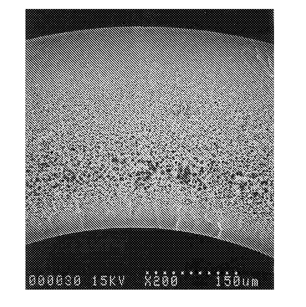
[0105]PES (Sumika EXCEL® 4800P manufactured by Sumitomo Chemtex) (19.0 wt. %), PVP (Kolidone® K30 manufactured by BASF) (3.0 wt. %), NMP manufactured by Mitsubishi Chemical Corporation (35.1 wt. %) and TEG manufactured by MITSUI CHEMICALS, INC. (42.9 wt. %) were mixed and dissolved at 80° C. for four hours to form a homogenous solution. The obtained solution was decompressed at from an atmospheric pressure to −700 mmHg. Immediately afterward, the system was sealed so as not to change the composition of the solution due to the volatilization of the solvent or the like, and the solution was left to stand for two hours so as to be defoamed. The resulting solution was used as a membrane-forming solution. A mixture of NMP (34.875 wt. %), TEG (42.675 wt. %) and RO water (22.5 wt. %) was prepared as an inner liquid. The membrane-forming solution and the inner liquid were discharged from the annular portion and the center portion of a double tube nozzle, respectively; afterward, the resulta...

example 2

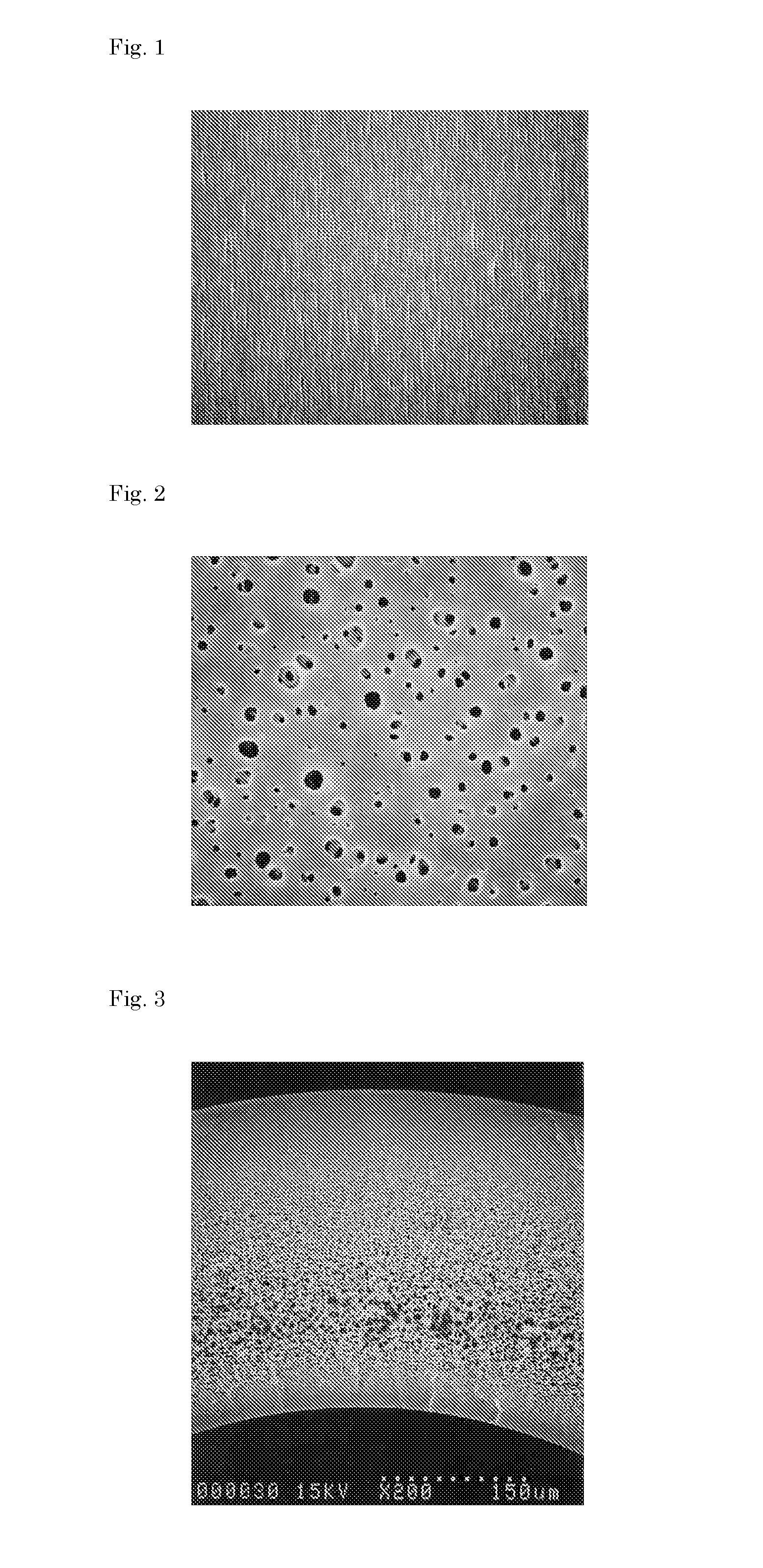
[0109]A hollow fiber membrane was produced using the same method as in Example 1, except that the membrane-forming solution was formed with PES (20.0 wt. %), PVP (K30) (5.0 wt. %), NMP (33.75 wt. %) and TEG (41.25 wt. %); the inner liquid was formed with a mixture of NMP (36.0 wt. %), TEG (44.0 wt. %) and RO water (20.0 wt. %) and a different condition was used to feed the hollow fiber membrane to the coagulating bath. The obtained hollow fiber membrane was wound up. In the coagulating bath, three cylindrical guides with diameters of 100 mm were arranged to gradually change the feeding direction of the hollow fiber membrane to pull it out from the coagulating bath. More specifically, the feeding direction of the hollow fiber membrane was changed at the curvature radius of 50 mm, and at three turning points. The immersion depth for the hollow fiber membrane in the coagulating bath was a maximum of 800 mm, and the feeding distance for the hollow fiber membrane in the same bath was 2,0...

example 3

[0111]A hollow fiber membrane was produced using the same method as in Example 1, except that the temperature of the external coagulating liquid was set to 40° C. The inner diameter and the thickness of the obtained hollow fiber membrane were 1,180 μm and 340 μm, respectively. Table 1 shows the results.

[0112]Flux was measured using the same method as in Example 1. Flux sustainability and recoverability by washing were both high, i.e., 81% and 90%, respectively. The structure of the hollow fiber membrane was the same as that in Example 1. The size change of the inner surface of the hollow fiber membrane in the direction along the cross section was measured according to ((|B|−|A|) / membrane thickness×100(%)), with the result of 7.0%.


PUM

PropertyMeasurementUnit
Temperatureaaaaaaaaaa
Pressureaaaaaaaaaa
Pressureaaaaaaaaaa

Abstract

The present invention provides a hollow fiber membrane for treating liquids. When used for a hollow fiber membrane module for refining a fermented liquid such as beer or wine, the hollow fiber membrane exhibits a high filtration performance per unit area thereof, with reduced clogging of the membrane. The membrane performance is sufficiently recovered by washing.
The present invention is a hollow fiber membrane for treating liquids, wherein a ratio of Flux 120 to Flux 30 is 0.45 or higher when filtration is performed by supplying a solution having a turbidity of 20 NTU into a hollow fiber membrane having an internal diameter of 500 to 1500 μm and a membrane thickness of 100 to 500 μm with a transmembrane pressure of 1.5 bar, the Flux 30 being flux 30 minutes after the start of the filtration, the Flux 120 being flux 120 minutes after the start of the filtration.

Description

TECHNICAL FIELD[0001]The present invention relates to a polymeric porous hollow fiber membrane for use in the treatment of liquids in the food field, the medical field, the semiconductor field, the energy field and the water treatment field. More specifically, the present invention relates to a hollow fiber membrane for treating liquids that exhibits high filtration performance with respect to wine yeast liquids, reduces clogging of the membrane, and improves recoverability of membrane performance by washing.BACKGROUND ART[0002]Diatomaceous earth has been used in the food field, particularly in the process of treating fermented liquids, such as the removal of yeast fluids, solid matter, colloids or the like from beer or wine after fermentation. However, the use of diatomaceous earth incurs several problems including the unconfirmed safety of diatomaceous earth, the disposal of used diatomaceous earth, which cannot be incinerated, and the high disposal cost for the large amount of di...

Claims


Application Information

Patent Timeline
IPC IPC(8): B01D69/08
CPCB01D69/02B01D69/081C02F1/444B01D2325/04B01D2325/022
Inventor OGAWA, HIROFUMIKATO, NORIAKIYOKOTA, HIDEYUKIMORITA, JUNSUKE
Owner TOYO TOYOBO CO LTD
Why Eureka
Try Eureka