Rfid Tag Substrate For Metal Component

a technology of rfid tags and substrates, applied in the field of rfid tags, can solve the problems of inability to give sufficient information, inability to read, and fixed limits as means of indicating and recognizing commodity information, so as to reduce the size of the main body of the tag, avoid the influence of metals on communication characteristics, and ensure the length of the antenna

Inactive Publication Date: 2010-09-02
TOYO SEIKAN KAISHA LTD
View PDF18 Cites 75 Cited by
  • Summary
  • Abstract
  • Description
  • Claims
  • Application Information

AI Technical Summary

Benefits of technology

[0171]As a result, the tag main body can be reduced in size, a necessary antenna length can be assured, and an influence of a metal on communication characteristics can be avoided. The tag becomes indistinctive in appearance, and the appearance of t...

Problems solved by technology

As a result, an indication area, a size of a character, or the number of characters is limited, and a problem that sufficient information cannot be given arises.
When the barcode has a scratch or a stain, it cannot be read.
Furthermore, since an amount of information that can be encoded in the form of a barcode is limited, there is a fixed limit as means for indicating and recognizing commodity information like the example of indication using characters.
Meanwhile, when such an RFID tag is disposed to a resin container like a PET bottle, it is readily affected by contents, e.g., water in the container.
Further, when the RFID tag is disposed to a metal container, e.g., an aluminum can, a steel can, or a pouch container, it is affected by electroconductive properties of the metal container, and hence the RFID tag has a problem that a communication distance varies or accurate wireless communication is disabled.
Specifically, when a metal is present immediately behind the RFID tag, a signal transmitted from a reader/writer cannot recognize an antenna of the RFID tag, performance of the antenna is considerably deteriorated, and an energy of electric waves cannot be received by the antenna of the RFID tag.
Therefore, when the RFID tag is disposed to a metal container or it is attached to a PET bottle having, e.g., drinking water filled therein, performance of the RFID tag is deteriorated, thus disabling accurate wireless communication in some cases.
As a result, a size of the entire tag is increased, thereby making it difficult to reduce a size of the tag.
Therefore, when the tag is to be disposed to a metal container, for example, a thermal loss that an electromagnetic wave produced by an antenna portion is absorbed into the metal container side occurs, thus deteriorating communication characteristics of the tag.
First, the method of using, e.g., a spacer to separate the RFID tag from a container by a predetermined distance can reduce an influence of moisture or a metal. However, a thickness of a substrate on which the tag is mounted is increased (e.g., approximately 30 mm in case of an RFID tag using 2.45 GHz). When the tag is disposed to a container, it ...

Method used


Image

  • Rfid Tag Substrate For Metal Component
  • Rfid Tag Substrate For Metal Component
  • Rfid Tag Substrate For Metal Component

Examples


first embodiment

[0206]As a first embodiment according to the present invention, a preferred embodiment of an RFID tag substrate and an RFID tag including this RFID tag substrate according to the present invention will now be explained with reference to FIGS. 1 to 12.

[RFID Tag Substrate]

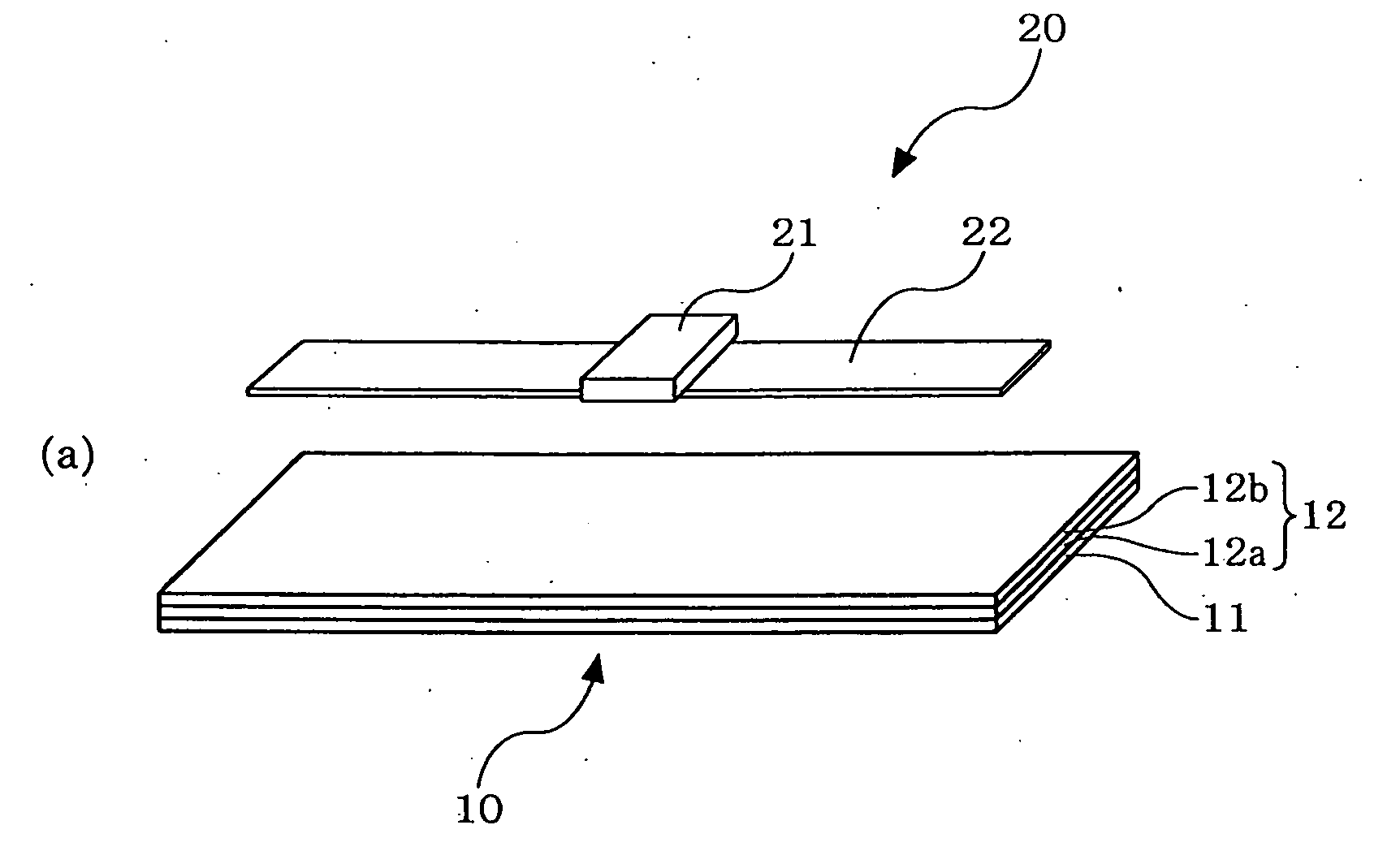
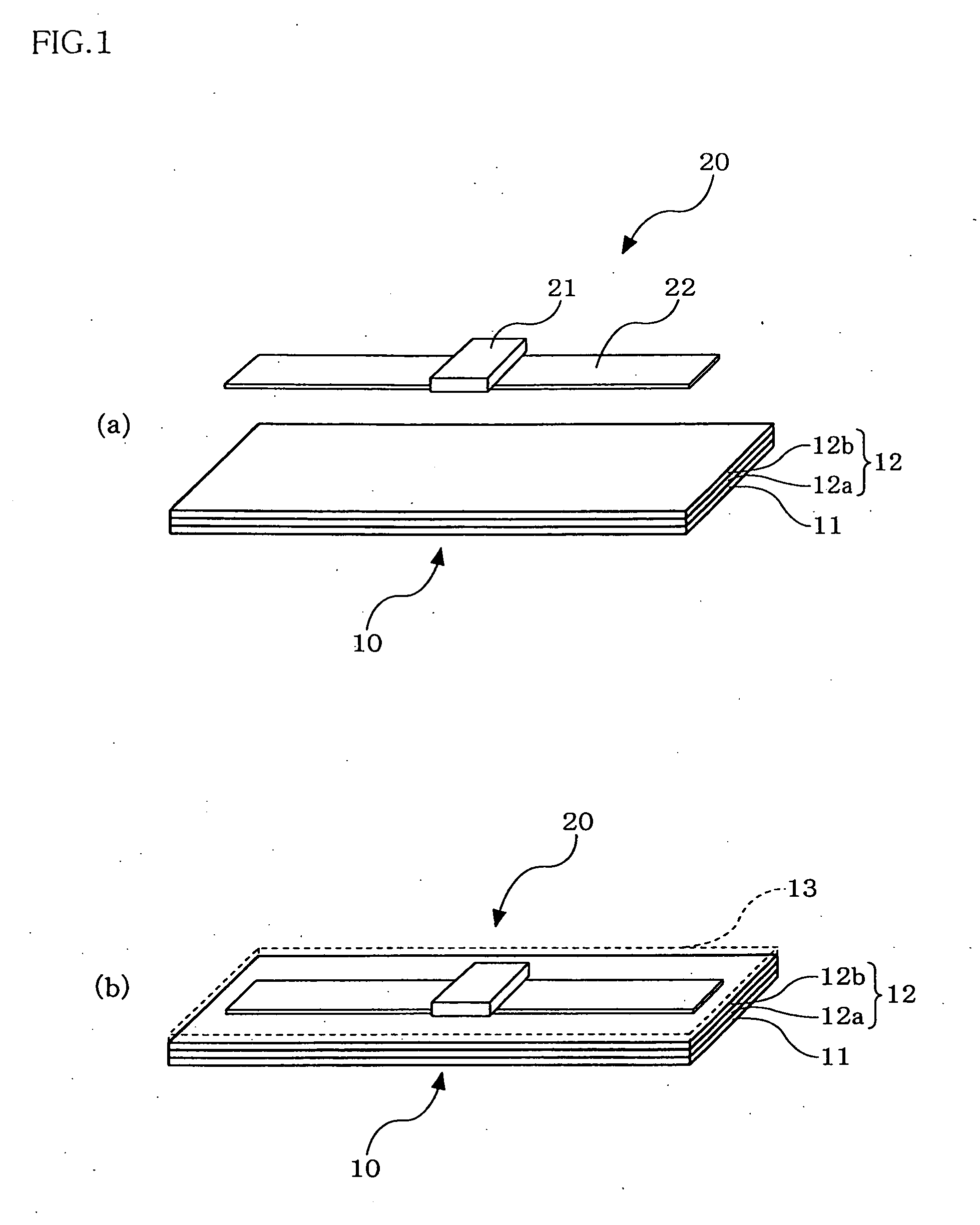
[0207]FIG. 1 are primary part perspective views schematically showing an RFID tag substrate according to an embodiment of the present invention, wherein (a) shows a state before an RFID tag is mounted and (b) shows a state where the RFID tag is mounted.

[0208]As shown in the drawings, an RFID tag substrate 10 according to this embodiment is a substrate that has an RFID tag 20 mounted thereon to constitute a part of the tag, and the RFID tag 20 that performs wireless communication with a reader / writer (not shown) is disposed at a predetermined position on a substrate surface.

[0209]Specifically, the RFID tag substrate 10 includes a substrate layer 11 and a functional layer 12, the RFID tag 20 including an IC chip 21 and...

example 2

[0357]A coating material obtained by mixing 350 parts by weight of an Al powder (an average particle diameter: 9.5 μm, an aspect ratio: 67.8) in 100 parts by weight of a resin component in a polyurethane-based binder (manufactured by Nippon Polyurethane Industry Co., Ltd.) was applied to a PET film having a thickness of 12 μm, and this structure was dried (three minutes in an oven at 130° C.) to manufacture a substrate. A thickness of the coating film was 30 μm.

[0358]A dielectric constant and a permeability of the coating film were substantially equal to those in Example 1.

[0359]As a result of conducting the same communication test as Example 1, a communication distance was 98 mm when a substrate lamination thickness was 0.94 mm.

example 3

[0360]An RFID tag (a coating film thickness: 50 μm, a lamination thickness: 0.92 mm, an operating frequency: 2.45 GHz) manufactured like Example 1 was attached to a side wall of a PET bottle filled with 500 ml of water to execute a communication test. As a result, a communication distance was 90 mm, and good communication characteristics were obtained without being affected by contents.


PUM


Abstract

The present invention provides an RFID tag substrate in which communication characteristics of an RFID tag do not vary by an influence of contents in a container, the communication characteristics of the RFID tag are not deteriorated even if a metal container is used, the communication characteristics of the RFID tag can be excellently maintained irrespective of a material or contents of a container, and the tag can be reduced in thickness/size, and which can use a general-purpose RFID tag as it is and is suitable for a microwave type RFID tag that uses a UHF band or a frequency band of, e.g., 2.45 GHz in particular.
There is provided an RFID tag substrate 10 on which an RFID tag 20 that performs wireless communication with a reader/writer is disposed, comprising: a substrate layer 11; and a functional layer 12 formed of a high-dielectric-constant layer 12a and a high-permeable layer 12b having different characteristics, wherein the functional layer having predetermined relative dielectric constant and relative permeability is provided, and a product of the relative dielectric constant and the relative permeability is not smaller than 250.

Description

BACKGROUND OF THE INVENTION[0001]1. Field of the Invention[0002]The present invention relates to an RFID tag substrate that is disposed to a container of drinks or foods to perform wireless communication between a reader / writer, and more particularly to an RFID tag substrate for a metal component that can maintain good communication characteristics of an RFID tag irrespective of a material or presence / absence of contents of a container and is suitable for an RFID tag adopting an electric wave mode, and to an RFID tag including this tag substrate.[0003]Further, the present invention relates to a metal lid provided to a metal container, e.g., an aluminum can or a steel can, and more particularly to a metal lid with an RFID tag to which the RFID tag that effects wireless communication with a reader / writer is attached, and to a metal container including this metal lid.[0004]Furthermore, the present invention relates to a metal article formed of a metal container or the like, e.g., an al...

Claims


Application Information

Patent Timeline
IPC IPC(8): G06K19/077
CPCG06K19/07749G06K19/07771H01Q1/2225G06K19/0723H01Q15/00H01Q15/14H01Q1/38B65D2203/10G06K19/07
Inventor KIKUCHI, TAKAYUKISOTOBAYASHI, KENMORI, MASAYUKI
Owner TOYO SEIKAN KAISHA LTD
Why Eureka
Try Eureka