
Cryogenic system for neon production

a cryogenic system and neon technology, applied in the field of cryogenic systems, can solve the problems of degrading the separation performance of the double-turbine distillation system, and the function and operation of the crude neon tower does not have any effect on the normal operation

Inactive Publication Date: 2010-09-02
BERNSTEIN JOSEPH THEODORE
View PDF2 Cites 17 Cited by
  • Summary
  • Abstract
  • Description
  • Claims
  • Application Information

AI Technical Summary

Benefits of technology

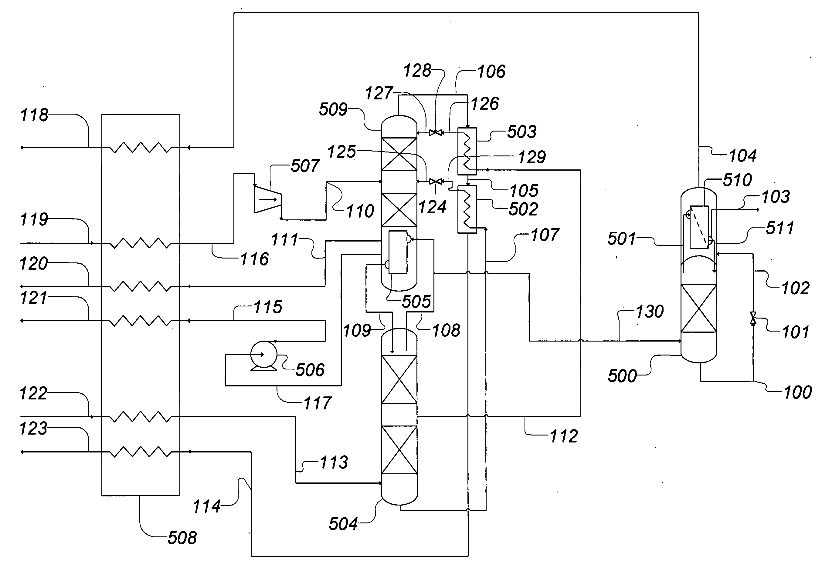
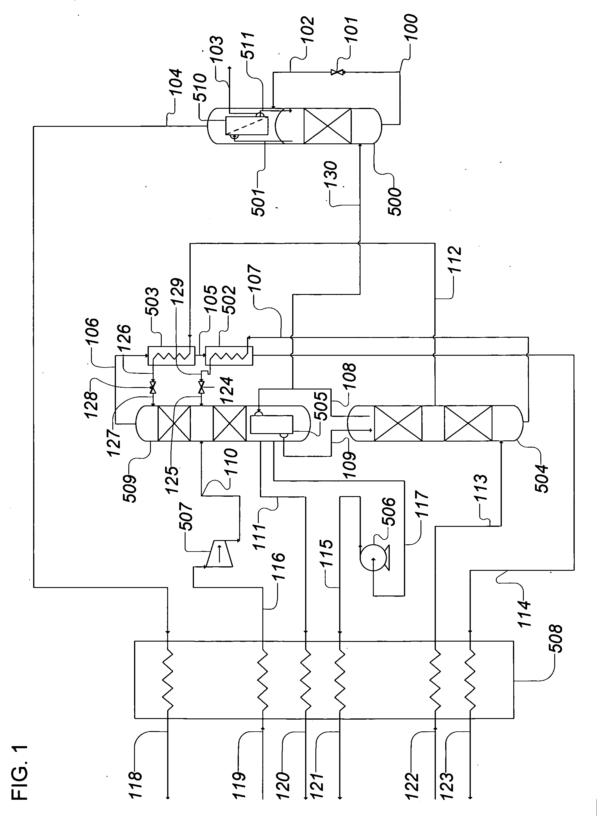
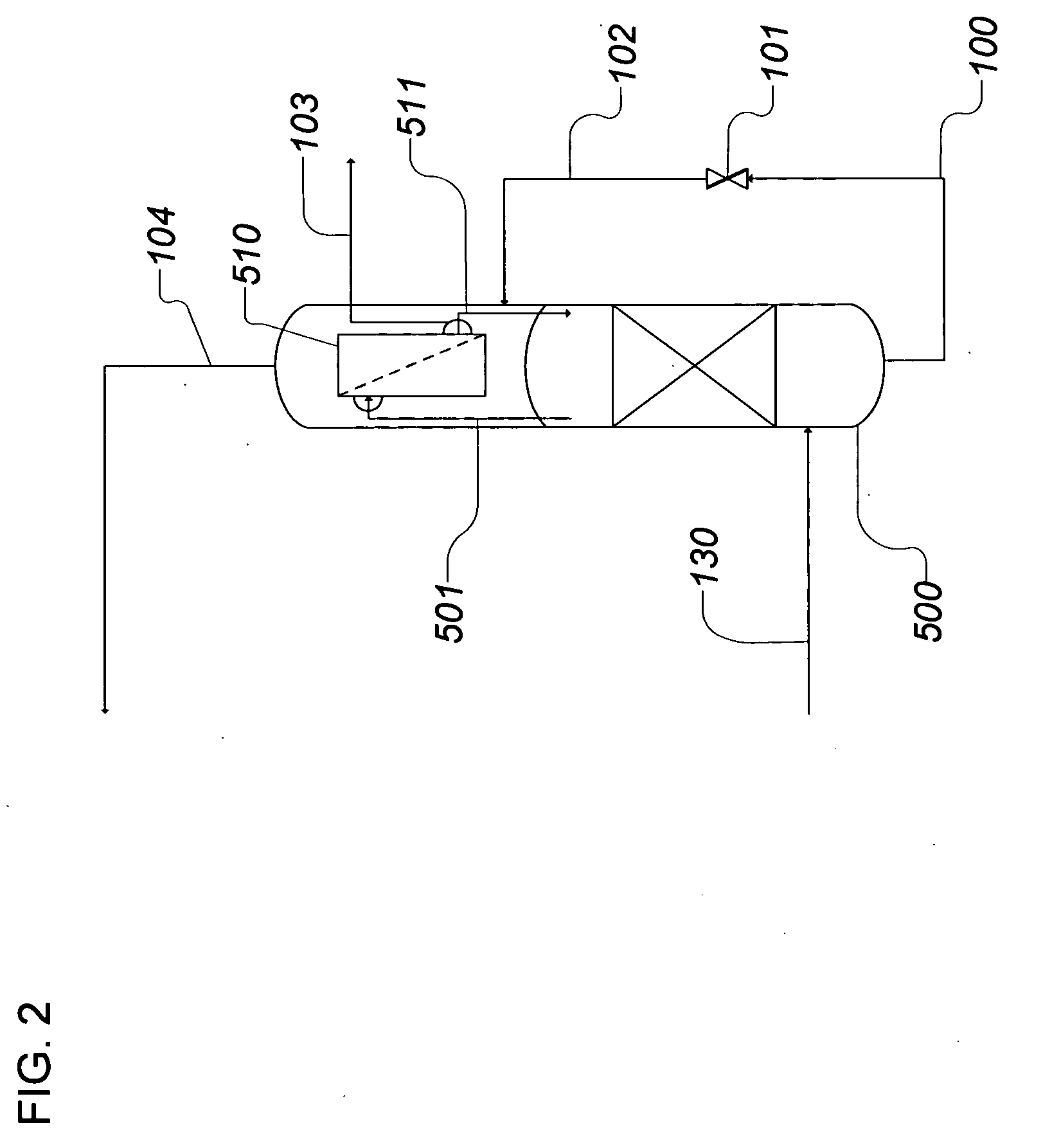
[0022]C.) Other than that nitrogen product stream originating at the top of the high-pressure distillation column, which is the feed stream to the crude neon recovery distillation column, there is no connection of streams to or from the

Problems solved by technology

Such withdrawal of liquid nitrogen can degrade the separation performance of the double tower distillation system.B.)
Because of this lack of connection, the function and operation of the crude neon tower does not have any effect on the normal operation of the double tower distillation system.

Method used


Image

  • Cryogenic system for neon production
  • Cryogenic system for neon production
  • Cryogenic system for neon production

Examples


first embodiment

[0029]In FIG. 1, ambient air, compressed to a pressure above the high-pressure tower pressure and after pre-purification to remove condensable components such as carbon dioxide and moisture, enters the feed-product main heat exchanger 508 as stream 122, and after cooling leaves as stream 113, and enters the bottom of the high pressure tower 504. An additional air feed stream 119 may also enter the main heat exchanger 508 and after cooling leave the main heat exchanger 508 as stream 116, which enters the expander 507 and after reduction in temperature leaves the expander as stream 110, which enters the low pressure tower 509. From the top of the high-pressure tower 504, a nitrogen-rich stream 108 enters the reboiler-condenser 505, and is condensed to form stream 109 which provides liquid reflux at the top of the high-pressure tower 504. A nitrogen vapor product stream 130 is withdrawn from the vapor stream 108 leaving the top of the high-pressure tower and entering the reboiler-conde...

second embodiment

[0037]In the second stage neon enrichment tower 512 the liquid nitrogen at the bottom of neon enrichment tower 512, stream 131, is reduced in pressure in valve 132 so that the resulting stream 133 is at a pressure below atmospheric pressure and the resulting vapor stream 135, resulting from the evaporation of the liquid nitrogen in the cold side of neon tower condenser 514, is directed to a vacuum pump 138 or other means of maintaining stream 135 at a pressure level below atmospheric pressure. In FIG. 3, the vapor nitrogen stream 135, evaporated from the second stage neon tower condenser 514, is warmed in heat exchanger 136, and the resulting stream 137 is maintained at a suitable pressure below atmospheric pressure by vacuum pump 138 and the resulting stream 139 is exhausted to the atmosphere. In the operation of the second stage neon enrichment tower 512, a supplemental liquid nitrogen stream 516 may be supplied through the valve 517 to provide an additional liquid nitrogen stream...


PUM


Abstract

A method and apparatus for the recovery of crude neon in or as part of a cryogenic air separation system wherein a neon recovery tower recovers crude neon from a nitrogen product stream originating from the top of the high pressure tower, and wherein the cooling for condensing in the neon recovery tower is provided by evaporating the liquefied nitrogen product from the bottom of the neon tower after the nitrogen liquid passes through a pressure reducing valve.

Description

CROSS-REFERENCE TO RELATED APPLICATIONS[0001]This application claims the benefit of provisional patent application No. 61 / 209,011 filed 2009 Mar. 2 by the present inventor and claims the benefit of provisional patent application No. 61 / 216,879 filed 2009 May 23 by the present inventor.FEDERALLY SPONSORED RESEARCH[0002]Not applicable.SEQUENCE LISTING[0003]Not applicable.BACKGROUND[0004]1. Field of Invention[0005]This invention relates to a cryogenic process for recovering crude neon in a double tower cryogenic air separation plant.[0006]2. Prior Art[0007]As used herein the term “column” means a distillation or fractionation column, i.e., a contacting column wherein liquid and vapor phases are countercurrently contacted to effect separation of a fluid mixture by contacting of the vapor and liquid phases on a series of vertically spaced trays or plates mounted within the column or on packing elements such as structured or random packing.[0008]As used herein the term “high-pressure towe...

Claims


Application Information

Patent Timeline
IPC IPC(8): C01B23/00
CPCF25J3/0409F25J3/04303F25J2215/32F25J3/04642F25J2200/32F25J3/04412
Inventor BERNSTEIN, JOSEPH THEODORE
Owner BERNSTEIN JOSEPH THEODORE
Learn More