Semiconductor device
- Summary
- Abstract
- Description
- Claims
- Application Information
AI Technical Summary
Benefits of technology
Problems solved by technology
Method used
Image
Examples
example 1
Type A, n-Si
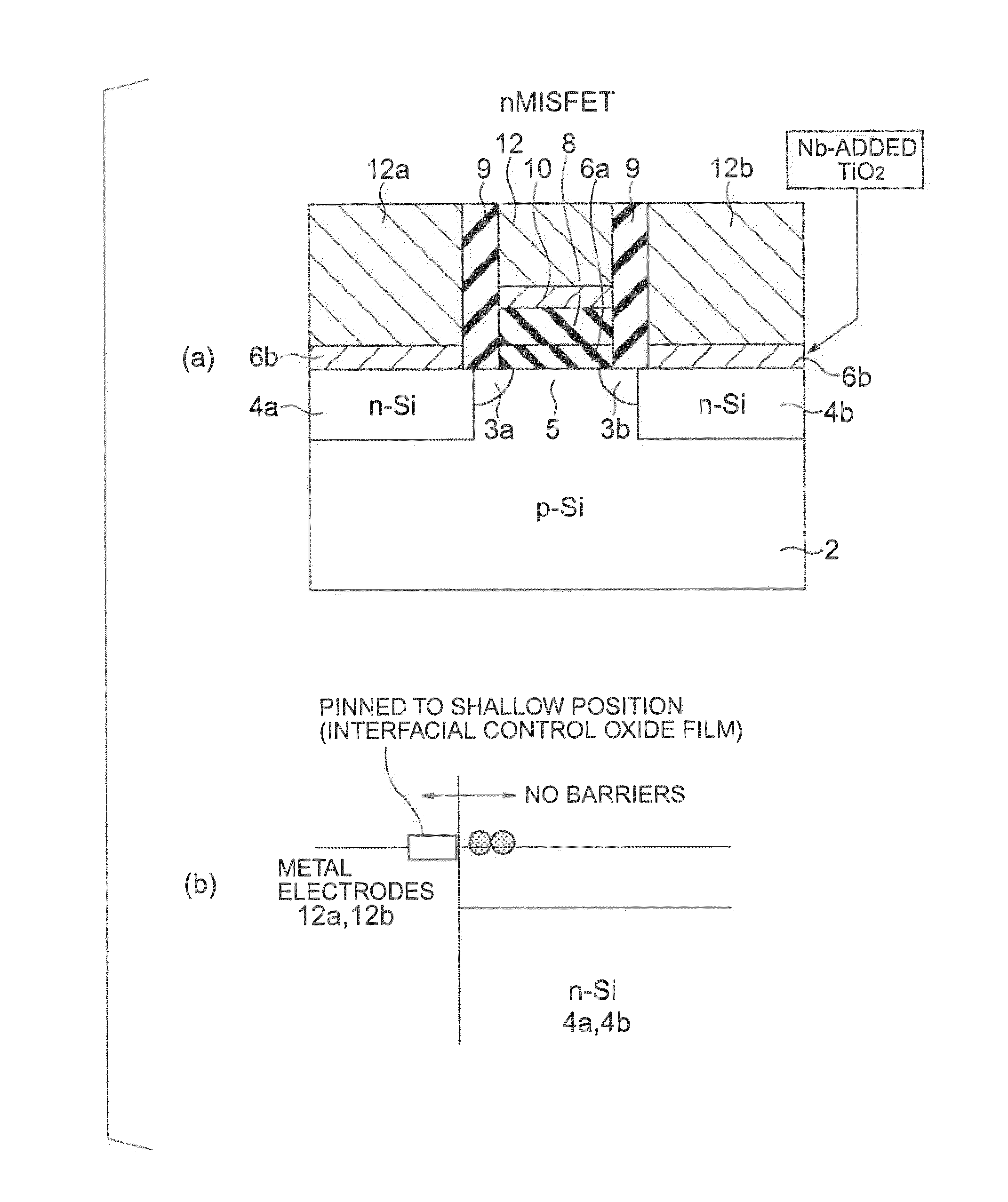
[0222]FIGS. 22(a) and 22(b) show a semiconductor device of Example 1 of the present invention. As shown in FIG. 22(a), the semiconductor device of this example has a stacked structure formed with a W-added TiO2 film 42 on an n-type silicon substrate 22, and a metal film 44 made of W and formed on the TiO2 film 42. The W added to TiO2 is an additional material of Type-A that forms a level in the band in a position higher than the bottom of the conduction band of Si when added. Through the addition of W, a junction with the n-type Si substrate without a barrier (a barrier-less junction) is formed.
[0223]The semiconductor device of this example is formed in the following manner. First, a TiO2 film is formed by sputtering on the n-type Si substrate 22, and a W film is formed by sputtering on the TiO2 film. After that, 1050° C. annealing is performed in vacuum, and 450° C. FGA (Foaming Gas Annealing) is performed in a H2 atmosphere. Through this thermal process, W diffuses int...
example 2
Type-A, n-Ge
[0252]FIGS. 25(a) and 25(b) show a semiconductor device according to Example 2 of the present invention. As shown in FIG. 25(a), the semiconductor device of this example has a stacked structure formed with a W-added TiO2 film 50 on an n-type Ge substrate 48, and a metal film 52 made of W and formed on the TiO2 film 50. The W added to TiO2 is an additional material of Type-A that forms a level in the band in a position higher than the bottom of the conduction band of Ge when added. A barrier-less junction with the n-type Ge substrate is formed.
[0253]The semiconductor device of this example is formed in the following manner. First, a TiO2 film is formed by sputtering on the n-type Ge substrate 48, and the W film 52 is formed by sputtering on the TiO2 film. The procedures to be carried out thereafter are the same as those of Example 1. The band lineup observed here is shown in FIG. 25(b). Simultaneous sputtering using the two targets of a TiO2 target and a W target is also ...
example 3
MIM Capacitor
[0277]Referring now to FIGS. 28 through 29(b), a semiconductor device of Example 3 of the present invention is described. The semiconductor device of this example is a MIM capacitor that has a stacked structure formed with a metal, an insulating material, and a metal. As shown in FIG. 28, a stacked structure is placed on a silicon substrate 60. In this stacked structure, a TiAlN buffer layer 61, a SrRuO3 electrode 62, a Mo-added TiON film (an interfacial control oxide film) 63, a Pb(Zr, TiO3 ferroelectric film 64, a Mo-added TiON film (an interfacial control oxide film) 65, and a SrRuO3 electrode 66 are stacked in this order. Each of the layers is formed by sputtering. Particularly, the Mo-added TiON films 63 and 65 are formed in an Ar / O2 / N2 atmosphere by simultaneous sputtering using a Mo target and a TiO2 target. After all the film formation is completed, 1050° C. annealing is performed in vacuum, and 450° C. FGA (Foaming Gas Annealing) is performed in a H2 atmosphere...
PUM
 Abstract
Description
Claims
Application Information
 - R&D
- Intellectual Property
- Life Sciences
- Materials
- Tech Scout
- Unparalleled Data Quality
- Higher Quality Content
- 60% Fewer Hallucinations
Browse by: Latest US Patents, China's latest patents, Technical Efficacy Thesaurus, Application Domain, Technology Topic, Popular Technical Reports.
© 2025 PatSnap. All rights reserved.Legal|Privacy policy|Modern Slavery Act Transparency Statement|Sitemap|About US| Contact US: help@patsnap.com


