
Four-cycle engine

a four-cycle engine technology, applied in the direction of machines/engines, liquid fuel feeders, output power, etc., can solve the problem of inability to realize practicable hcci operation

Inactive Publication Date: 2010-09-23
CD ADAPCO JAPAN +1
View PDF19 Cites 12 Cited by
  • Summary
  • Abstract
  • Description
  • Claims
  • Application Information

AI Technical Summary

Benefits of technology

[0011]In the invention of claim 1, the exhaust gas at a high temperature is sucked back from the first exhaust port and the secondary air at a low temperature is sucked from the second exhaust port, into the cylinder and therefore a first temperature layer at a high temperature and a second temperature layer at a low temperature can be formed in the cylinder to realize slow combustion even in a high load operation range and prevent knocking. Further, the engine has a structure simpler and more practical than a conventional device in which the intake gas is heated.
[0015]In the invention of claim 3, the secondary air can be supplied to the second exhaust port by opening / closing the open / close control valve at an optimal timing and in a desired amount to easily and surely form the first temperature layer and the second temperature layer in the cylinder.
[0017]According to the invention in claim 4, the compressed fresh air flows through to the second exhaust port side using the EGR overlap period during which both the intake valve and the second exhaust valve of the second exhaust port are open, to thereby supply the compressed fresh air into the second exhaust port, which is used as secondary air, resulting in a simple structure of the secondary air supply system.
[0018]Further, according to the invention in claim 5, the compressed fresh air at a pressure equal to or higher than an exhaust port internal pressure is supplied into the cylinders by dynamic effects of the intake and exhaust systems, and the compressed fresh air flows through to the second exhaust port side from the intake port side using the EGR overlap period during which both the intake valve and the second exhaust valve are open, to thereby supply the fresh air into the second exhaust port, which is used as secondary air, so that the secondary air supply system can be made simplest without the supercharger nor the secondary air pump, while supplying the secondary air.
[0023]According to the invention in claim 7, the mask member to restrain flow of the exhaust gas to the intake valve side is provided, whereby mixture of the exhaust gas and the fresh air in the cylinder can be suppressed to make the temperature difference between the first temperature layer and the second temperature layer larger and clear.
[0027]According to the invention in claim 9, the ratio of the fuel amount injected to the first temperature layer and the fuel amount injected to the second temperature layer is controlled, and thus controls of the ignition time, the speed of slow combustion, and the combustion temperature can be realized.

Problems solved by technology

Though the operation range of the HCCI engine can be widened by the above-described method, practical HCCI operation cannot be realized because the rate of pressure rise is too high in the high load operation range.

Method used


Image

  • Four-cycle engine
  • Four-cycle engine
  • Four-cycle engine

Examples


first embodiment

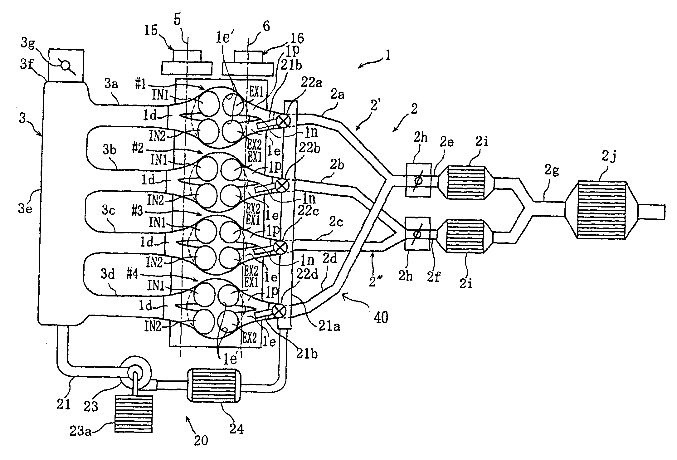
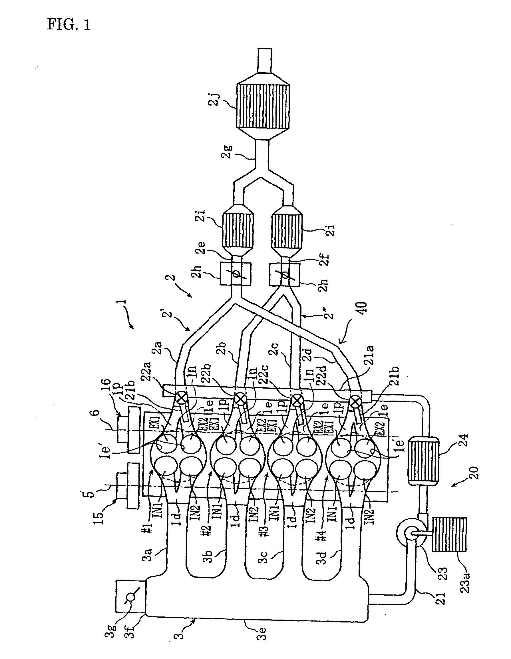
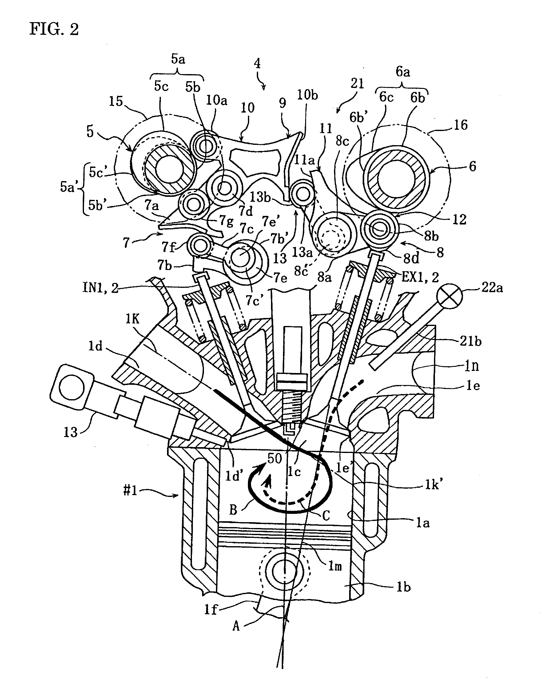
[0072]FIG. 1 to FIG. 7 are views for describing a four-cycle engine according to the present invention. FIG. 1 is an overall structural view. FIG. 2 is a cross-sectional side view of this engine. FIG. 3 is a schematic plan view of a valve system. FIG. 4 are schematic views of a switching system. FIG. 5 to FIG. 7 are graphs for describing operations.

[0073]In the drawings, numeral 1 denotes an HCCI engine based on a four-cylinder, four-valve DOHC gasoline engine. This engine 1 includes #1 cylinder to #4 cylinder. The #1 cylinder to #4 cylinder each have four valves in total: two intake valves IN1, IN2 and two exhaust valves EX1, EX2. Further, the engine 1 includes in-cylinder gasoline injection valves 13, and has a compression ratio set to 12 which is optimal for spark ignition combustion.

[0074]The order of ignition in the engine 1 is #1-#3-#4-#2 cylinders. The phase between the cylinders (ignition interval) is 180 degrees in crankshaft angles. Therefore, the phase between the #1 cyli...

second embodiment

[0120]In middle of the air introduction path 30 connected to a surge tank 3e of an engine 1 of the second embodiment, a main supercharger 31 driven by an electric motor or engine output is interposed, so as to supply fresh air compressed at a predetermined pressure to the engine 1. In addition, numeral 30a denotes a bypass detouring the main supercharger 31, numeral 30b denotes a bypass valve which opens / closes the bypass 30a, numeral 32 denotes an intercooler which decreases the temperature of compressed fresh air, and numeral 33 denotes an air cleaner.

[0121]Compressed fresh air from the main supercharger 31 is introduced into the cylinder bore of the #1 cylinder from the intake port 1d by opening of the intake valves in an intake stroke of the #1 cylinder. As shown in FIG. 12, near the end of this intake stroke, there is a relatively long overlap period in which the second exhaust valve EX2 starts EGR valve opening at a timing earlier than closing of the intake vales and thus the ...

third embodiment

[0127]FIG. 13 to FIG. 16 are views for describing the present invention. In these drawings, the same reference numerals as in FIG. 1, FIG. 5 and FIG. 10 denote the same or corresponding parts.

[0128]In an engine 1 of the third embodiment, a merging pipe 2e of a first exhaust system 2′ and a merging pipe 2g of a second exhaust system 2″ are connected to a turbocharger 36 having one common variable nozzle turbine. An intercooler 35 is interposed in an air path 34 connecting an air discharge port of the turbocharger 36 and a surge tank 3e. Further, a pressure sensor 2r is disposed on an exhaust branch pipe 2a.

[0129]Further, the engine 1 of the third embodiment has a secondary air supply system 20 having the same structure as that of the above-described first embodiment. This secondary air supply system 20 includes a secondary air supply path 21 connecting the surge tank 3e and the exhaust ports 1e, an auxiliary supercharger 23 and an intercooler 24 interposed in the secondary air suppl...


PUM


Abstract

A four-cycle engine (1) structured to introduce fresh air into a cylinder (1a) via an intake port (1d) opened / closed by intake valves (IN1, IN2) and suck exhaust gas back into the cylinder (1a) via an exhaust port opened / closed by exhaust valves (EX1, EX2), wherein the exhaust port has a first exhaust port (1p) and a second exhaust port (1e), and the exhaust gas is sucked in back from the first exhaust port (1p) and secondary air is sucked in from the second exhaust port (1e) to form, in the cylinder (1a), a first temperature layer (T1) at a high temperature mainly composed of the exhaust gas and a second temperature layer (T2) at a temperature lower than that of the first temperature layer (T1) mainly composed of the secondary air.

Description

TECHNICAL FIELD[0001]The present invention relates to a four-cycle engine structured to introduce fresh air into a cylinder via an intake port and to suck exhaust gas back into the cylinder via an exhaust port.[0002]Note that in Description of this application, air introduced into the cylinder via the intake port is referred to as fresh air, and air introduced into the cylinder via the exhaust port is referred to as secondary air.BACKGROUND ART[0003]Homogeneous Charge Compression Ignition (HCCI) engine is expected as means for realizing a fuel efficiency as high as the diesel engine while maintaining the low emission characteristics inherent in the gasoline engine. Note that fuel is supplied by injection near the compression top dead center in a normal diesel engine, whereas fuel is injected earlier into a combustion chamber or mixed with air in an intake port and introduced into a combustion chamber, and then the premixed gas is auto-ignited near the compression top dead center by ...

Claims


Application Information

Patent Timeline
IPC IPC(8): F02B3/00F02B47/08F02B33/00F01L1/34F02M69/04
CPCF01L13/0026Y02T10/20F01N3/32F02B23/104F02B33/34F02B33/42F02B47/08F02B2023/106F02B2075/027F02B2275/48F02D13/0207F02D13/0265F02D13/0269F02F1/4214F02M25/0726F02M25/0739Y02T10/121Y02T10/125Y02T10/142F01L2800/10F02M26/22F02M26/34Y02T10/12
Inventor HATAMURA, KOICHIYAMADA, TOSHIOMORITA, ATSUSHI
Owner CD ADAPCO JAPAN
Learn More