Radiation detector

a detector and radiation technology, applied in the field of radiation detectors, can solve the problems of complex disposed pluralities of electrodes or dynodes, inability to realize at a low cost, limited space, etc., and achieve the effects of low cost, high sensitivity, and simple detector structur

Inactive Publication Date: 2010-09-23
SHIMADZU CORP
View PDF2 Cites 11 Cited by
  • Summary
  • Abstract
  • Description
  • Claims
  • Application Information

AI Technical Summary

Benefits of technology

[0027]As described above, when compared with the detector using the photomultiplier, the construction of the present invention is quite thin and simple. Additionally, the detector of the present invention is different from the photomultiplier requiring a plurality of electrodes; hence, the structure of the detector of the present invention is simple, and the detector can be realized at a low cost.
[0028]In addition, when compared with the detector using the avalanche photodiodes, the expensive low noise amplifier or dedicated temperature adjusting mechanism performing a low temperature operation is not required.
[0029]In addition, the radiation detector with a quite high sensitivity is provided.

Problems solved by technology

However, the radiation detector of the examples in the prior art has the following problems.
For the detector in the PET device, there is a big problem under the situation that the space is limited.
In addition, a plurality of electrodes or dynodes is complicatedly disposed in the photomultiplier, which cannot be realized at a low cost.
However, the signal amplification degree of the avalanche photodiodes is 50-100 times, which is smaller than the amplification degree of the photomultipliers of 105˜106 times. Therefore, the avalanche photodiodes can be applied by using an expensive low noise amplifier and a dedicated temperature adjusting mechanism in the low temperature environment.
In addition, the luminescence wavelength of the scintillator LaBr3:Ce or LaCl3:Ce with high performance, high luminescence, and high speed is 300˜400 nm, which is a low wavelength band, and the quantum efficiency of the avalanche photodiodes in the wavelength band of 300˜400 nm is 40˜60%, such that the efficiency is poor.

Method used


Image

  • Radiation detector
  • Radiation detector
  • Radiation detector

Examples


embodiment

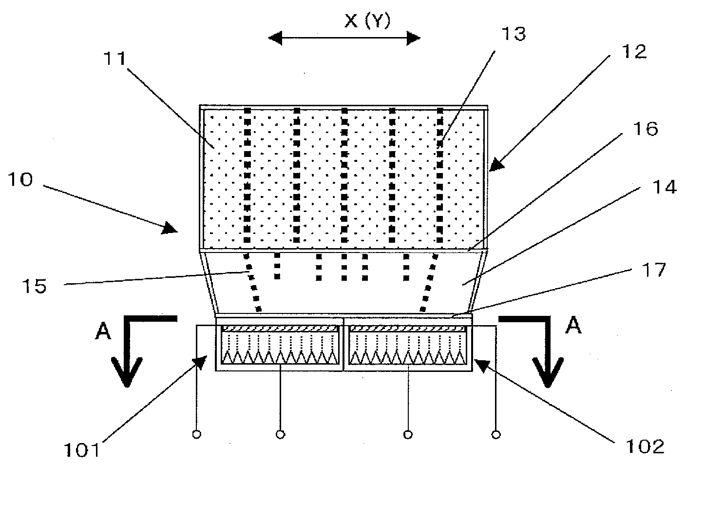
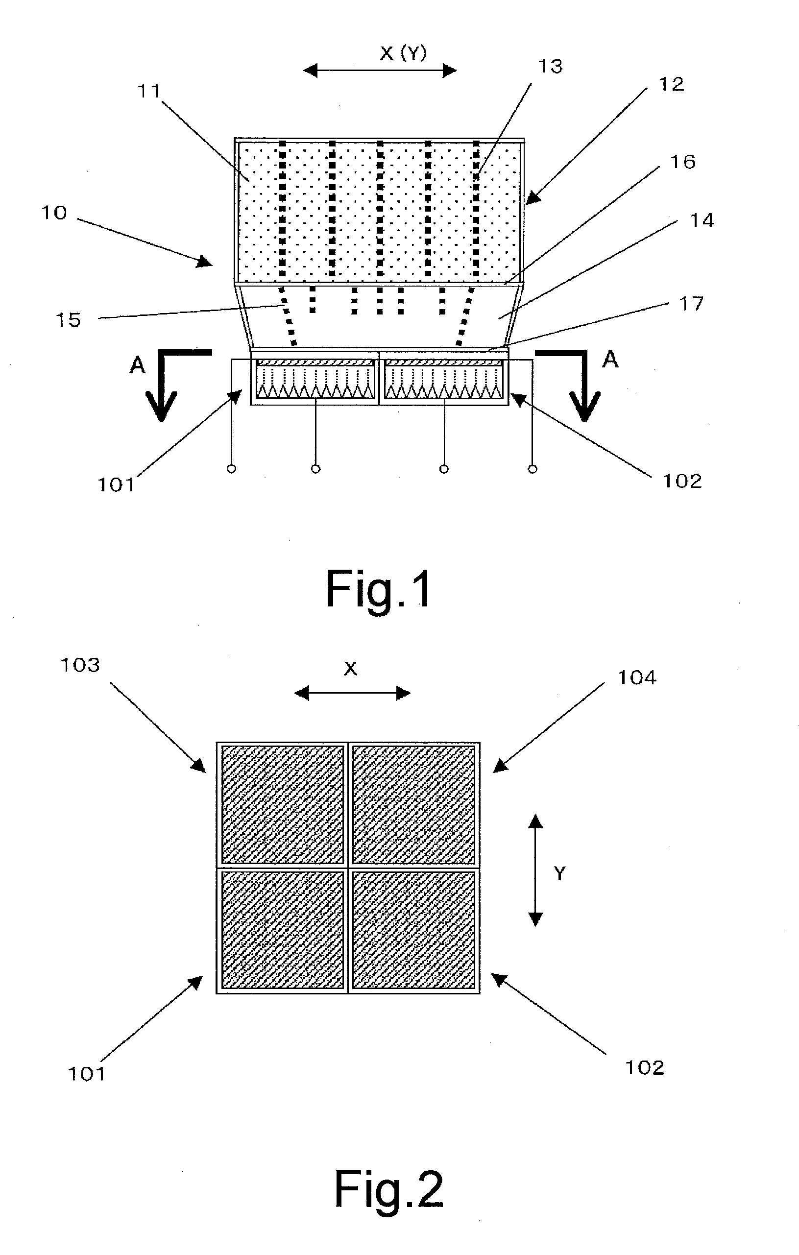
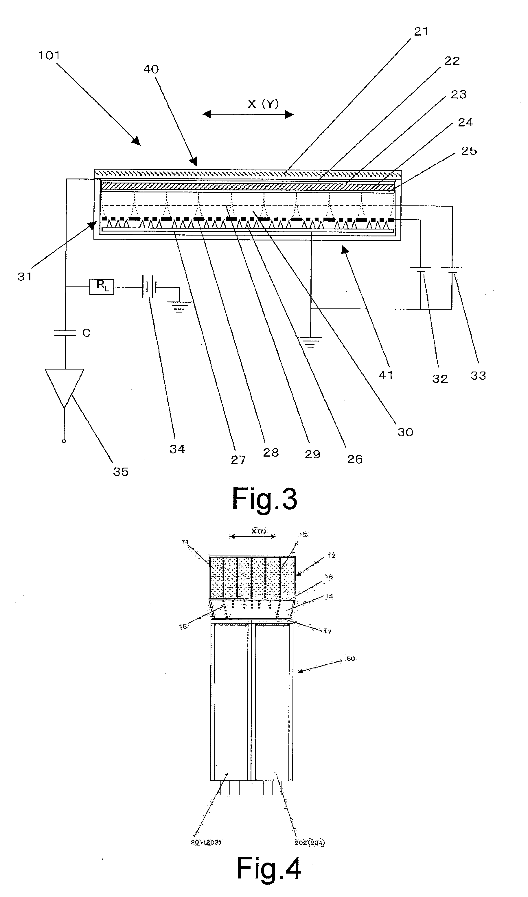
[0040](Embodiment) The drawings illustrate the structure of a radiation detector according to the present invention, and the detailed description thereof is provided according to the embodiment. FIG. 1 is a cross-sectional view in the X direction obtained by viewing a radiation detector 10 from the Y direction. In this embodiment, an isotropic voxel detector is described, so a cross-sectional view in the Y direction (side view) obtained by viewing the radiation detector 10 from the X direction also has the same shape as that of FIG. 1. The radiation detector 10 includes a scintillator array 12, which is divided, by appropriately inserting a light reflective material 13, into 36 scintillators 11 that are compactly arranged in two dimension in a manner of six scintillators in the X direction and six scintillators in the Y direction; a light guide 14, which is optically combined with the scintillator array 12 and is divided into a plurality of small blocks, and includes embedded lattic...


PUM


Abstract

A thin radiation detector with a high sensitivity is described. The radiation detector has light receiving elements receiving lights emitted by scintillators, performs a photoelectric conversion by using an avalanche multiplication film formed by amorphous selenium, and reads signals by using electron beams constantly discharged from a plurality of electron beam emitting sources called as a field emission array. The avalanche multiplication film formed by amorphous selenium is quite thin and has a simple structure, so it can be formed compactly and realized at a low cost. In addition, a signal amplification degree is approximately 1000 times, so an expensive low noise amplifier or a dedicated temperature adjusting mechanism is not required, and a quantum efficiency is sufficient for a wavelength of 300˜400 nm.

Description

BACKGROUND OF THE INVENTION[0001]1. Field of the Invention[0002]The present invention generally relates to a radiation detector, for example, applied to a positron emission tomography (PET) device, a single photon emission computed tomography (SPECT) device, or other medical diagnostic devices, in which the device detects a radioactive ray (gamma ray) discharged from radioactive isotopes (RIs) that are administered to a to-be-tested object and accumulated in a target site, so as to obtain an RI distribution tomogram of the target site.[0003]2. Description of Related Art[0004]The radiation detector includes scintillators that become luminescent by the incident gamma ray discharged from the to-be-tested object, and photomultipliers converting the luminescence of the scintillators to a pulsed electric signal. For the radiation detector of the prior art, the scintillators one-by-one correspond to the photomultipliers. However, the following method is being adopted recently, in which the...

Claims


Application Information

Patent Timeline
Patent Type & Authority Applications(United States)
IPC IPC(8): G01T1/20
CPCG01T1/1642H01J31/49H01L27/1446H04N5/32H01L31/107H01L31/117H01L31/0272
Inventor TONAMI, HIROMICHIOHI, JUNICHI
Owner SHIMADZU CORP
Why Eureka
Try Eureka