Entertainment system for use during the operation of a magnetic resonance imaging device

a technology for entertainment systems and magnetic resonance imaging, which is applied in the field of entertainment systems for patients during the operation of magnetic resonance imaging devices, can solve the problems of increasing patient anxiety and discomfort, entertainment systems moving in the magnetic field and affecting the patient's comfort, so as to reduce patient anxiety, calm and entertain patients, and improve the efficiency of the mri system

Inactive Publication Date: 2010-09-23
HUGHES BRIAN
View PDF37 Cites 34 Cited by
  • Summary
  • Abstract
  • Description
  • Claims
  • Application Information

AI Technical Summary

Benefits of technology

[0015]An object of the present invention is a portable video player with video glasses and headphones, which a patient wears in the strong magnetic field of an MRI system to calm and entertain the patient. With more patients calm and remaining still during their MRI procedure, MRI system productivity may increase. The present invention's video glasses reduce patient anxiety when inside the small magnet bore of the MRI system. The present invention's headphones reduce the loud noise from the MRI system and allow the patient to hear audio entertainment. Another objective of the present invention is an entertainment system that requires no installation at the MRI facility. The present invention is battery powered and worn by the patient. Another objective of the present invention is a lower cost entertainment system for patients in a MRI system. Another objective of the present invention is downloading (e.g., by way of purchasing or otherwise) the entertainment (e.g., media) either directly (e.g., WiFi, or otherwise) or by transferring (e.g., from a computer or otherwise) to the storage medium (e.g., memory card) of the entertainment system for playing in the entertainment system. The present invention is based on lower-cost, commercially available, consumer entertainment systems.
[0017]In the present invention, the video glasses have LCD displays and lenses in front of each of the patient's eyes. A printed circuit board in the control unit regulates the LCD displays, and converts the signal from the control unit into imaging signals for the LCD displays. The patient inserts corrective lenses between the LCD display and the patient's eyes for optical corrections. The video glasses enclose the patient's face, eliminating the visual distraction of the MRI magnet bore. Padding at the edge of the video glasses provides a comfortable fit on the patient's face. Adjustable headphone arms connect the headphones to the video glasses and hold the video glasses on the patient's face in front of the patient's eyes.
[0018]In the present invention, the entertainment system headphones have sufficient passive noise attenuation to reduce the MRI system noise significantly. In addition, the entertainment system headphones have optional active noise cancellation to further reduce the MRI system noise. The entertainment system headphones have non-magnetic speakers, which generate the audio entertainment. Pads at the edges of the headphones reduce noise getting to the patient ears, and the pads make the headphones more comfortable for the patient. Adjustable headphone arms connect the headphones to the video glasses and hold the headphones firmly against the patient's ears.
[0019]In the present invention, a Faraday shield encloses the entire electronics of the entertainment system. The Faraday shield enables the entertainment system to operate in the MRI system. The Faraday shield reduces the RF emission from the entertainment system sufficiently so that the emissions do not significantly degrade with the MRI image quality. The Faraday shield reduces the MRI system pulses from entering the entertainment system and significantly degrading the entertainment or damaging the entertainment system. The control unit, video glasses, and headphone electronics are inside conductive shields. Shielded cables connect these three shields together. Typical Faraday shielding, such as solid metal and metal braiding around a cable, a control unit, a user interface, a video component, an audio component, a storage medium, or otherwise, or any combination thereof may not be suitable in a MRI environment during the operation thereof because they may include too much metal content which may result in anomalies in the MRI images and heating from eddy current as discussed herein. As such, Faraday shielding formed of a conductive metal mesh provides reduced metal content, which may be desirable. The design carefully minimizes the amount of metal in order to minimize anomalies in the MRI images and heating from eddy current that may be caused by dense volumes (e.g., large volumes) of metal material. However, too fine of a metal mesh (low gage wire and / or larger openings between the wires) may form a brittle shielding that may break upon being deformed. For example, a Faraday shielding layer around a cable may crack with flexing, thereby rendering emitting RF signals to or from the cable, which may be form undesirable MRI artifacts and / or eddy currents. Furthermore, using a thicker metal mesh may also by undesirable because of the additional metal content, which may result in MRI anomalies / artifacts. One novel solution to overcome the unpredictable balance between flexibility / rigidity and the amount of metal content in the Faraday shielding is to utilize multiple layers of mesh separated by an insulating layer to resist any contact by the mesh layer. Multiple layers of the mesh provide the rigidity to withstand deformation while isolating each mesh layer from one another to reduce anomalies in the MRI images and / or reduce heating from eddy currents relative to a single mesh or fewer mesh layer having a similar mesh configuration and a similar amount of metal content (e.g., volume). Insulation around the cables protects patients against potential local heating. The insulation also reduces kinking of the cables and potential damage that may result from kinking.
[0020]A self-contained portable entertainment system requires one or more doors for replacing the battery and entertainment. The entertainment can be replaced by exchanging the entertainment media or downloading new entertainment to the system by cable or wirelessly. Forming a door that seals the Faraday shield adequately was very difficult and required several experiments to find an adequate solution. One novel solution is to dispose the mesh on the door to overlap significantly and contact the control unit chassis mesh. The novel solution requires low RF resistance between the door mesh and the control unit chassis mesh.
[0022]Mesh shielding may not be desirable for shielding over components that require visual communication. For example, mesh across a viewing screen such as a monitor or TV viewing screen or a viewing lens such lens form glasses or LCD-lens may degrade the image quality. One novel solution to shield across a lens such as a LCD-lens unit is to provide an optically transparent conductive film, which does not significantly degrade the LCD image. For example, a transparent conductive film may be used to adequately shield the RF signals while increasing visual image quality relative to a mesh (e.g., metal mesh) material for use across a viewing lens / screen as a Faraday shield in an MRI environment. After careful grounding, the transparent conductive film provided a sufficient Faraday shield for the integral entertainment in a MRI during the operation thereof. Low pass RF filters, before each cable connection, further reduce RF energy from entering or leaving the entertainment system.

Problems solved by technology

The MRI magnet bore is small, especially in the head-coil, and induces claustrophobic feelings in many patients.
These loud noises add to the anxiety and discomfort of the patient.
First, the strong fields generated by the MRI device must not prevent the normal operation of an entertainment system or cause the entertainment system to move in the MRI system's large magnetic field.
Third, the entertainment system must not emit sufficient RF energy to degrade the MRI image quality.
For example, the prior art generally taught that batteries may not operate safely in an MRI, because the eddy current may heat and discharge the batteries.
It is appreciated that the large magnetic field produced by the MRI may undesirably affect electrical circuits, such magneto resistance, and hall-effect voltages.
As such, the prior art provides insufficient teachings that storage mediums such as a memory card and / or the corresponding circuits to read the data and create video signal may be operable in the high magnetic field of a MRI.
These systems retrofit the MRI system with the optical fibers or optical transfer scheme, which is rather expensive to install.
The long length of fiber from the MRI control room to the MRI system attenuates the image and degrades the image quality.
These systems do not readily accommodate different positions of the patient.
The patient is still aware of the surrounding MRI system with these entertainment systems; thus, the systems may not adequately distract the patient.
In addition, the lighting in the MRI magnet room can make the display more difficult to watch.
These entertainment systems require expensive installations in the MRI magnet room and bring the entertainment signal through the MRI magnet room Faraday shield.
All entertainment systems that bring in the signal by cables have the potential problem of snagging and damaging the long cables.
Many of the systems described in prior art do not allow for optical correction.
Long lengths of pipe to bring an audio signal from outside degrade the audio signal quality by attenuating the high frequency audio signal.
Prior entertainment systems for use in an MRI system are complicated because they transmit the entertainment media from the MRI control room to the MRI magnet room via penetration of the room shielding.
These MRI facilities modifications are expensive and stop operation of the MRI facilities during modification.
However, these consumer portable video players may be unsuitable for use in a MRI system because they contain ferromagnetic materials, they emit RF energy that can interfere with a MRI image quality, they may be affected by the RF pulse of a MRI system, they may not be securely attached to the user allowing their use in any position, or otherwise.

Method used


Image

  • Entertainment system for use during the operation of a magnetic resonance imaging device
  • Entertainment system for use during the operation of a magnetic resonance imaging device
  • Entertainment system for use during the operation of a magnetic resonance imaging device

Examples


Embodiment Construction

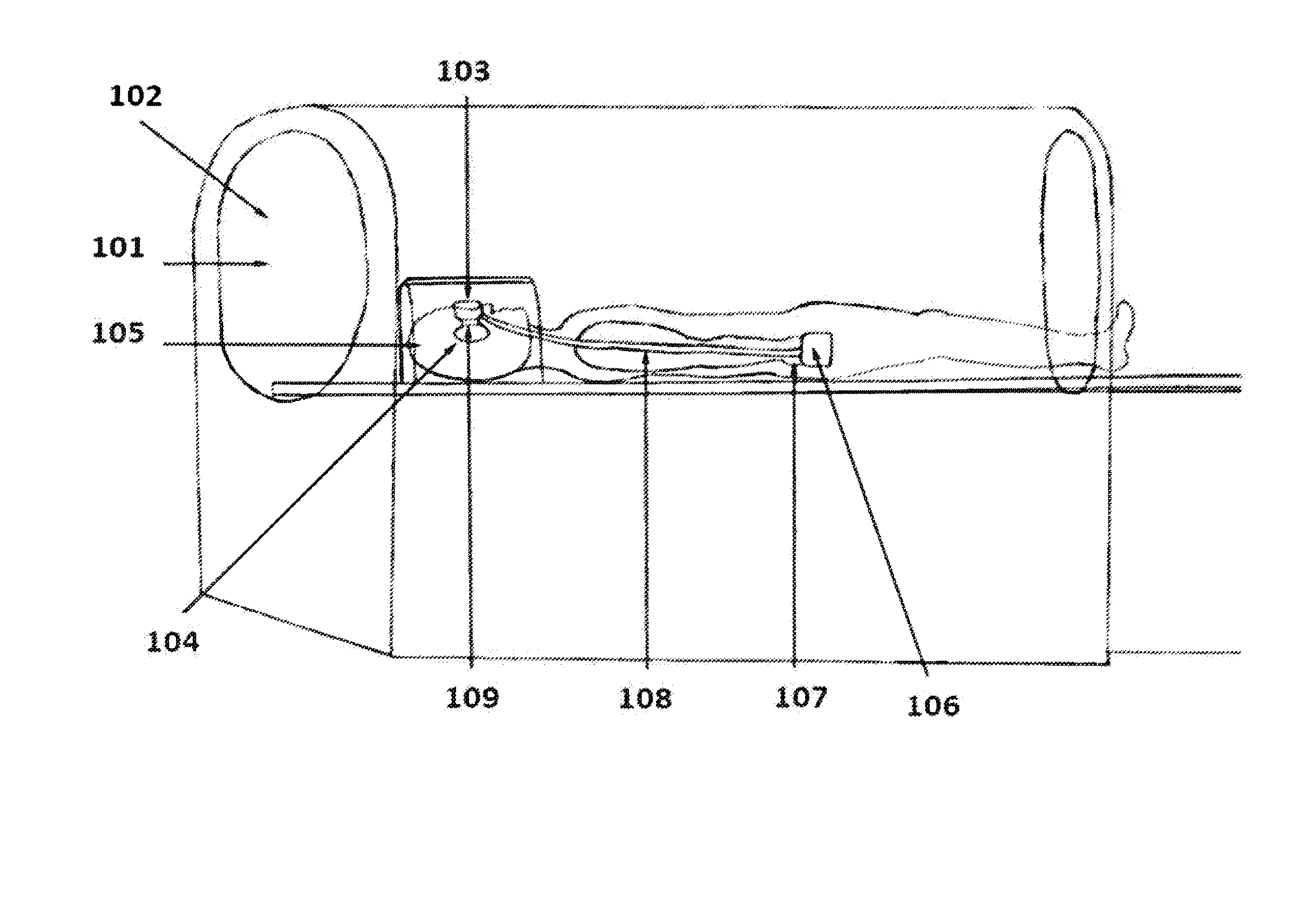
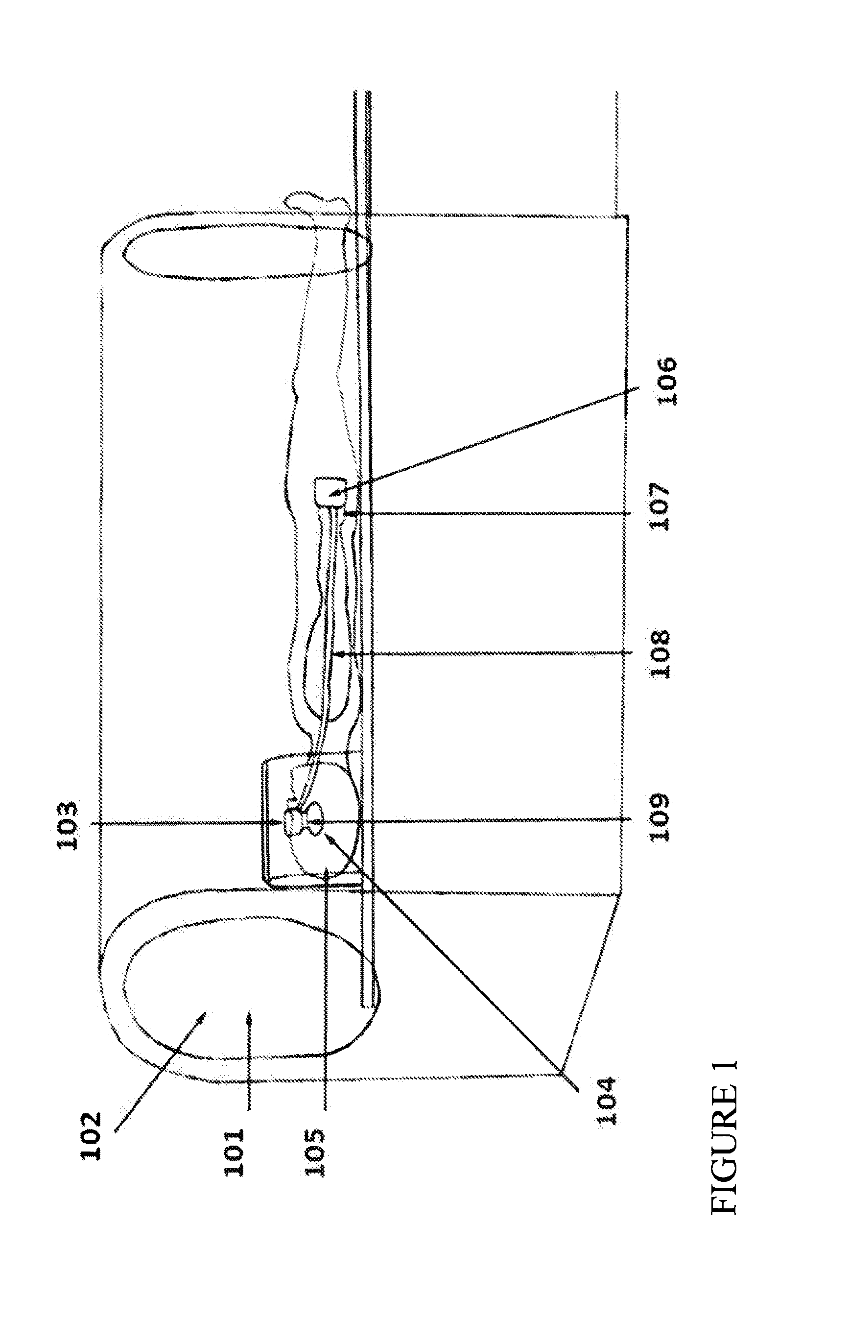
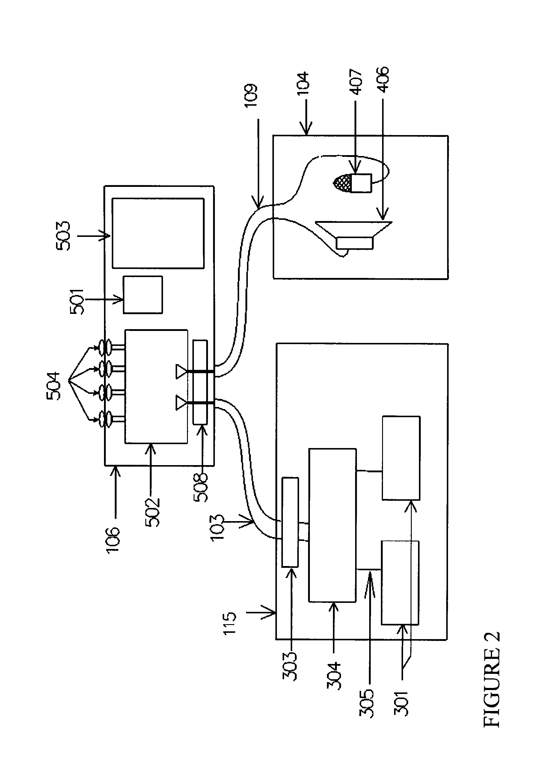
[0031]The present invention is predicated upon methods and devices for entertaining a patient during the operation of a magnetic resonance imaging (MRI). Referring to the drawings, this is achieved through the use of a self-contained entertainment system 100. As shown in FIG. 1, a patient 101 is positioned within a magnet bore 102 of the MRI. The entertainment system includes a video component such as video glasses 103 and an audio component such as headphones 104 mounted to the patient's head 105. The entertainment system further includes a control unit 106 for controlling (e.g., driving) the video and / or audio components. It should be appreciated that because of the limited amount of space within the magnetic bore, the patient may have limited or no movement that would allow a hand of the patient to be easily moved to or near the head of the patient during MRI imaging. As such, in one embodiment, the control unit 106 may be positioned generally near the patient's hand 107 for inte...


PUM


Abstract

An entertainment system for use with a magnetic resonance imaging (MRI) device that includes video glasses and headphones. A Faraday shield encloses the entertainment system to reduce adequately RF signals from entering or leaving the entertainment system. The entertainment system may have non-ferromagnetic RF low-pass filters between parts of the system, such as the control unit and the video glasses, to reduce higher RF signals from entering or leaving those parts. To replace the battery and or entertainment media, a person opens the entertainment system's Faraday shield when not MRI imaging or outside the MRI magnet room. The door has an Faraday shield overlapping the system Faraday shield and making low resistance RF contact. The entertainment system has a minimal amount of ferromagnetic material so that it may operate within the high magnetic field of the MRI magnet bore with minimal performance degradation. The entertainment system uses non-ferromagnetic speakers in the headphone. Passive ear protection and noise cancellation reduce the loud noise of the MRI system heard by the patient to a level where the patient can hear the entertainment. The entertainment system includes a charger for the rechargeable batteries.

Description

CLAIM OF PRIORITY[0001]This application claims priority from U.S. Provisional Application 61 / 161,971, filed Mar. 20, 2009, incorporated herein by reference.FIELD OF THE INVENTION[0002]The present invention relates to methods and devices for the entertainment of a patient during the operation of a magnetic resonance imaging device generally.BACKGROUND OF THE INVENTION[0003]In the medical field, magnetic resonance imaging (MRI) is a commonly used non-invasive technique to diagnose the medical condition of a patient. Typically, the MRI system operator places the patient within the central bore of large homogeneous magnetic field and the MRI system subjects the patient to a set of gradient magnetic fields and RF pulses. The MRI system measures the very small RF signals emitted from nuclei in the patient, and processes the information to reconstruct an image of the part of the patient's body in the MRI system. The images produced by the MRI have very small amplitude RF signal in the freq...

Claims


Application Information

Patent Timeline
Patent Type & Authority Applications(United States)
IPC IPC(8): H04N5/60H04N5/64G10K11/16G06F3/048H05K9/00
CPCH04N5/64A61B5/055A61M21/00A61M2205/8206H04N21/4325A61M2021/0027H04N21/414A61B5/0033A61B5/0046A61B5/7405A61B5/742
Inventor HUGHES, BRIANHUGHES, RYAN A.
Owner HUGHES BRIAN
Why Eureka
Try Eureka