Polarization conversion device, polarized illumination optical device, and liquid crystal projector

a technology of polarization conversion and optical device, which is applied in the direction of instruments, polarising elements, projectors, etc., can solve the problems of high manufacturing cost, deterioration of polarization conversion efficiency, and high cost of crystal itself, and achieves efficient conversion, excellent thermal resistance, and low cost.

Inactive Publication Date: 2010-09-30
FUJIFILM CORP
View PDF3 Cites 8 Cited by
  • Summary
  • Abstract
  • Description
  • Claims
  • Application Information

AI Technical Summary

Benefits of technology

[0016]With the above configurations, it is possible to obtain a polarization conversion device which is excellent in thermal resistance and can be manufactured at low cost. Moreover, when either one of the first and second linearly polarized light beams having the polarization directions perpendicular to each other is incident on the polarization conversion device, the either one can be efficiently converted into the other linearly polarized light beam. The retardation films used in the polarization conversion device can be manufactured using a normal deposition method of performing the deposition from a direction substantially perpendicular to the substrate surface. Accordingly, it is possible to obtain retardation films which have no cloudy part being apt to be generated by the oblique deposition, and which is also excellent in physical durability. Also, by using the above polarization conversion device as a polarization conversion device provided in an illumination optical system of a liquid crystal projector, linearly polarized light for illumination of a liquid crystal display panel can be obtained with high efficiency. As a result, it becomes possible to improve the contrast of a projected image.

Problems solved by technology

Accordingly, if the ½ wavelength plates are used near the light source for a long time, discoloration easily occurs and the polarization conversion efficiency is deteriorated.
However, not only the crystal itself is expensive, but also the manufacturing cost is high because the crystal should be processed while controlling the optical axis of the crystal precisely.
However, if the film thickness is increased up to a level at which the retardation film can be used as a ½ wavelength plate, the retardation film becomes clouded.
Particularly, a reduction in transmittance at the short wavelength side is noticeable, which would adversely affect the color balance.

Method used


Image

  • Polarization conversion device, polarized illumination optical device, and liquid crystal projector
  • Polarization conversion device, polarized illumination optical device, and liquid crystal projector
  • Polarization conversion device, polarized illumination optical device, and liquid crystal projector

Examples


Embodiment Construction

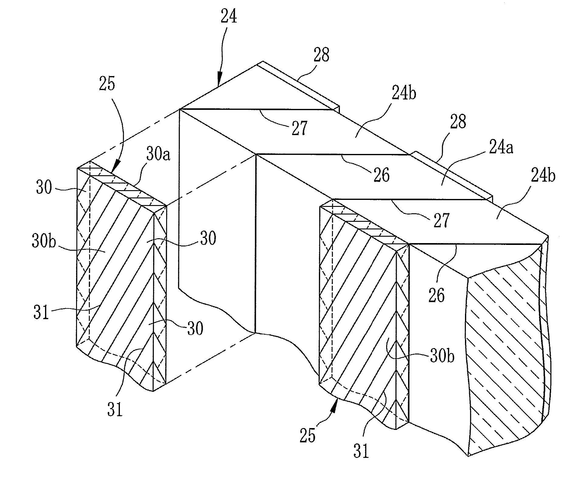
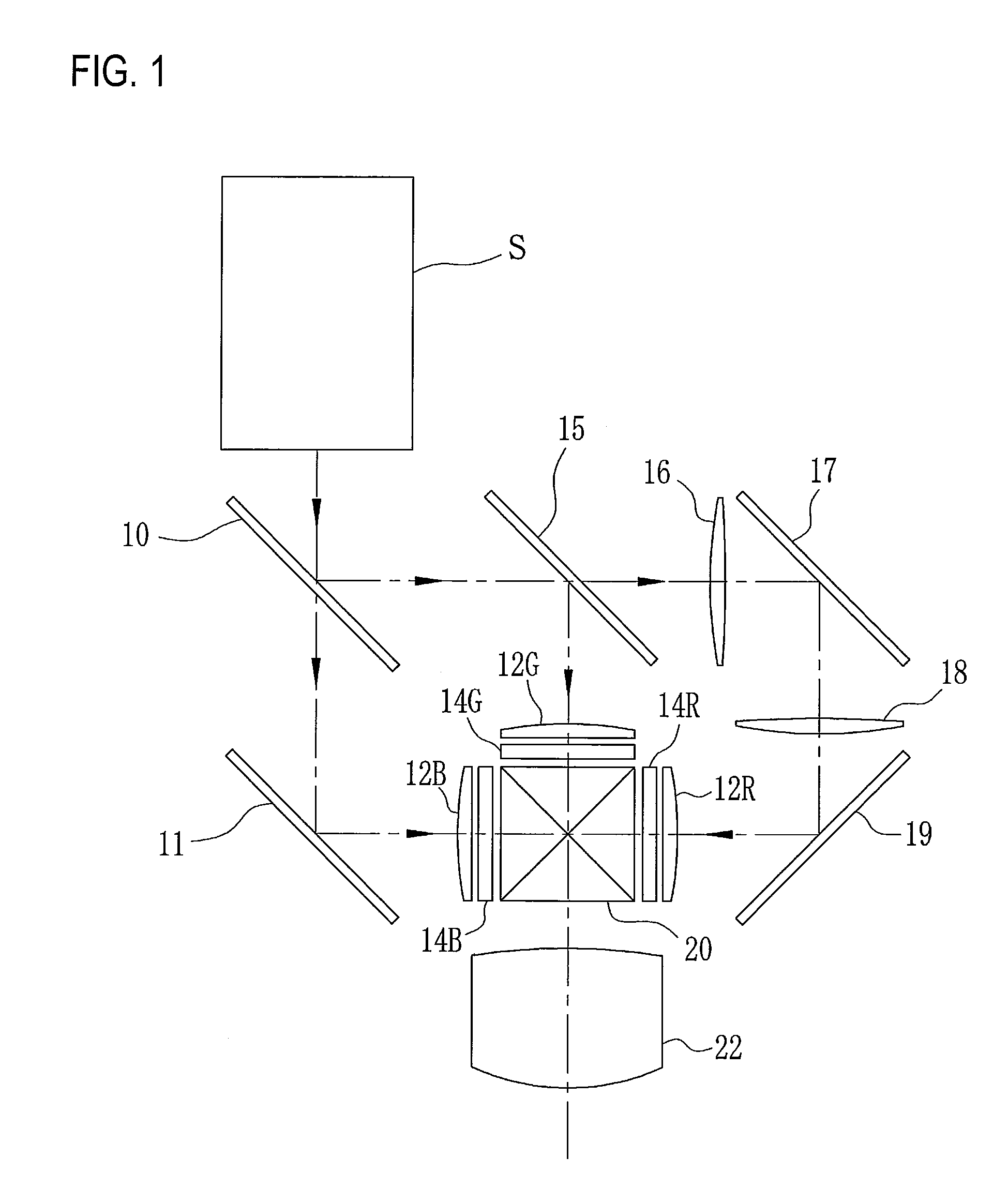
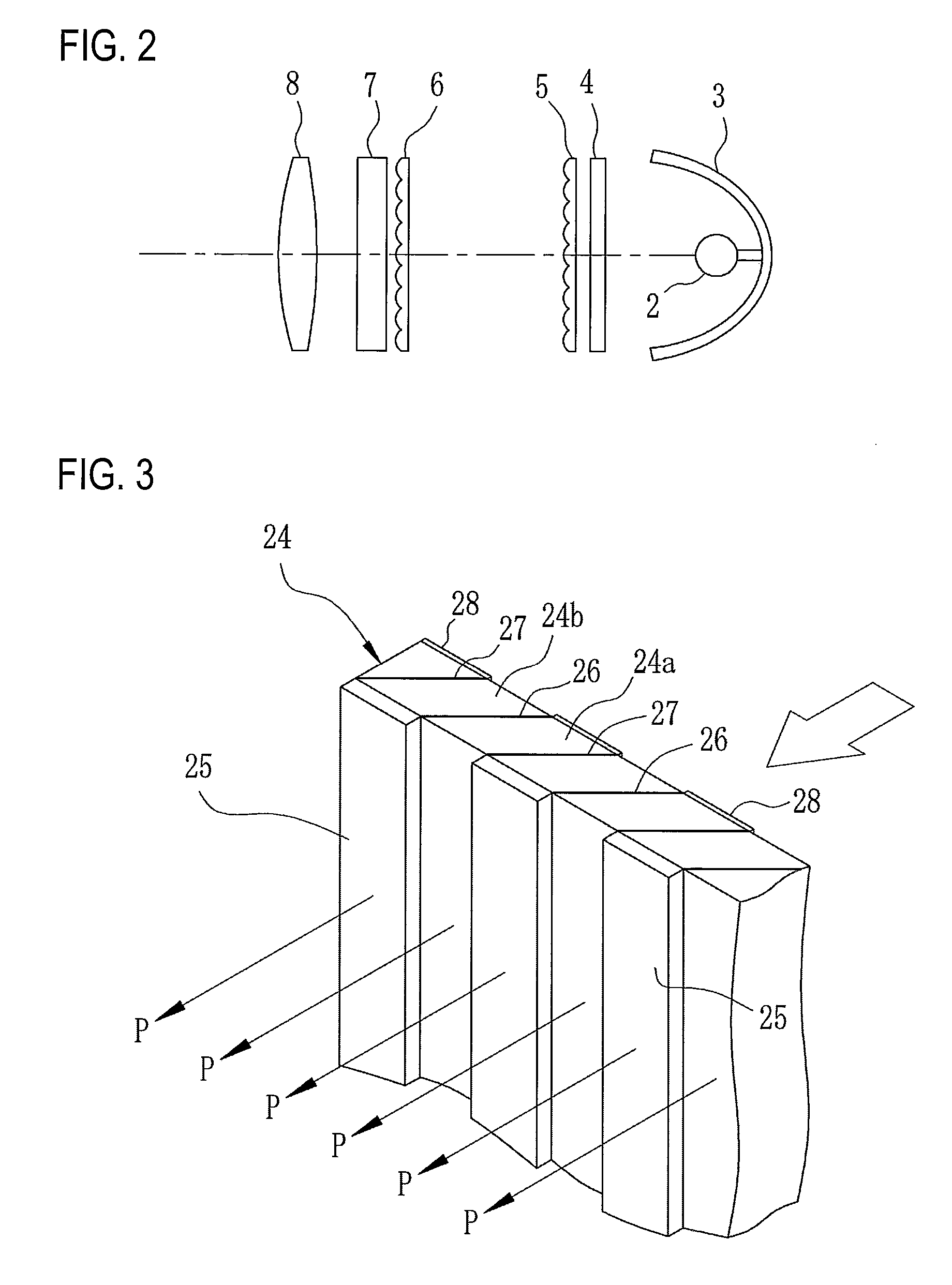
[0030]An optical system of a liquid crystal projector is schematically configured as shown in FIG. 1 including a light source device S. As shown in FIG. 2, the light source device S includes a high-intensity light source lamp 2, such as an ultrahigh-pressure mercury lamp, and the light source lamp 2 is used together with a reflector 3. A filter 4 for cutting infrared light and ultraviolet light is provided on an illumination optical path. Non-polarized illumination light beams in a visible range in which various polarized light beams are mixed are incident on a first microlens array 5 as substantially parallel beams. The first microlens array 5 is obtained by arranging plural microlenses in a rectangular matrix so as to follow the rectangular shape of a liquid crystal display panel, and forms a pseudo light source corresponding to the number of microlenses equivalently on a second microlens array 6 having the same structure.

[0031]The illumination light emitted from the pseudo light ...


PUM

PropertyMeasurementUnit
inside angleaaaaaaaaaa
angleaaaaaaaaaa
center wavelengthaaaaaaaaaa

Abstract

Polarizing split layers 26 and reflection layers 27 are provided on bonding surfaces between prism rods 24a and 24b. Polarization conversion devices 25 are bonded to an emission surface from which linearly polarized light being reflected by the polarizing split layers 26 and reflected by the reflection layer 27 are emitted. The polarization conversion devices 25 are formed by bonding plural prism rods 30 with side surfaces being inclined by 45° with respect to an incidence surface. Retardation films formed of dielectric multilayers are provided between the bonding surfaces to give a phase difference of a ½ wavelength to transmitted light. The retardation films and bonding borderlines 31 are inclined by 45° within a plane perpendicular to an optical axis of linearly polarized light so that an optical axis of the retardation film has an angle of 45° with respect to a polarization direction of the linearly polarized light.

Description

CROSS-REFERENCE TO RELATED APPLICATIONS[0001]This application is based upon and claims the benefit of priority from Japanese Patent Application No. 2009-76846 filed on Mar. 26, 2009; the entire contents of which are incorporated herein by referenceBACKGROUND OF THE INVENTION[0002]1. Technical Field[0003]The invention relates to a polarization conversion device which rotates a polarization direction of linearly polarized light by 90°, a polarized illumination optical device which converts non-polarized illumination light into illumination light of linearly polarized light having a fixed polarization direction by the polarization conversion device, and a liquid crystal projector which uses the polarized illumination optical device in an illumination optical system.[0004]2. Description of the Related Art[0005]Various kinds of liquid crystal projectors that illuminate an image, which is displayed on a liquid crystal display panel, with light from a light source lamp for projection onto ...

Claims


Application Information

Patent Timeline
Patent Type & Authority Applications(United States)
IPC IPC(8): G02F1/13357G02B27/28G02F1/13363
CPCG03B21/00G02B27/283G03B21/006
Inventor KAWAMURA, YOSHIJI
Owner FUJIFILM CORP
Why Eureka
Try Eureka