
Method for producing methane from biomass

a biomass and hydropyrolysis technology, which is applied in the direction of combustible gas production, combustible gas purification/modification, bulk chemical production, etc., can solve the problems of high capital expenditure of air separation plants, long time-consuming and labor-intensive conversion of biomass in anaerobic digesters, etc., and achieve fast pyrolysis and superior methane yields

Active Publication Date: 2010-10-07
GAS TECH INST
View PDF27 Cites 49 Cited by
  • Summary
  • Abstract
  • Description
  • Claims
  • Application Information

AI Technical Summary

Benefits of technology

[0006]It is one object of this invention to provide a method and apparatus for producing methane which provides superior methane yields when compared with conventional anaerobic digestion, gasification, or fast pyrolysis.
[0007]It is one object of this invention to provide a method and apparatus for producing methane which occupies a lower physical footprint than a comparable anaerobic digester or fast pyrolyzer. Conversion of biomass in an anaerobic digester takes a long time (20-30 days of residence time in the digester), requiring a very large anaerobic digester.
[0008]It is yet another object of this invention to provide a method and apparatus for producing methane which is less costly than conventional steam and oxygen pressurized gasification followed by methanation. Gasification is capital intensive because it is run at high temperatures, requires an air separation plant to produce the required oxygen, which air separation plant is capital intensive.

Problems solved by technology

Conversion of biomass in an anaerobic digester takes a long time (20-30 days of residence time in the digester), requiring a very large anaerobic digester.
Gasification is capital intensive because it is run at high temperatures, requires an air separation plant to produce the required oxygen, which air separation plant is capital intensive.

Method used


Image

  • Method for producing methane from biomass
  • Method for producing methane from biomass
  • Method for producing methane from biomass

Examples


Embodiment Construction

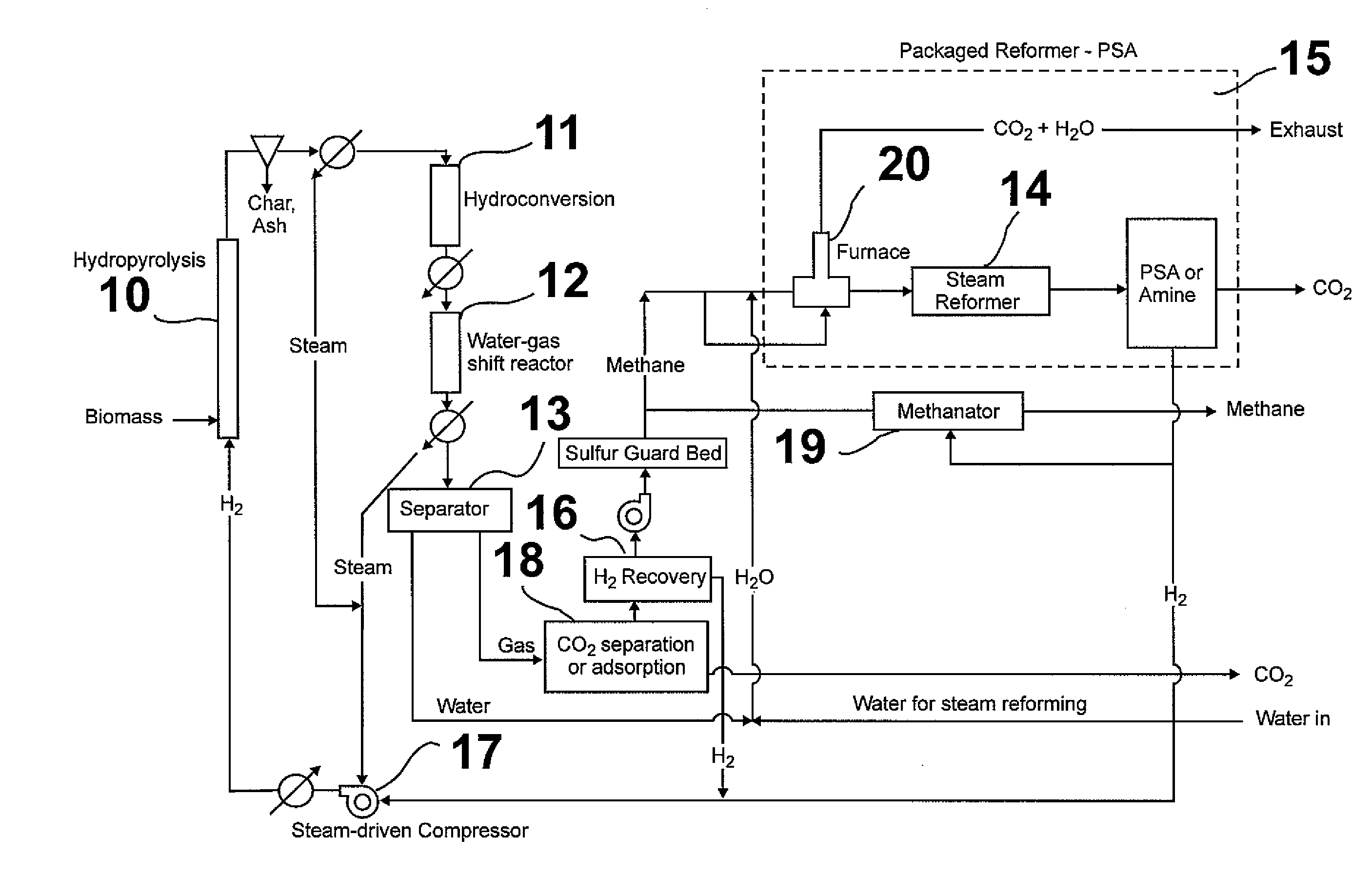
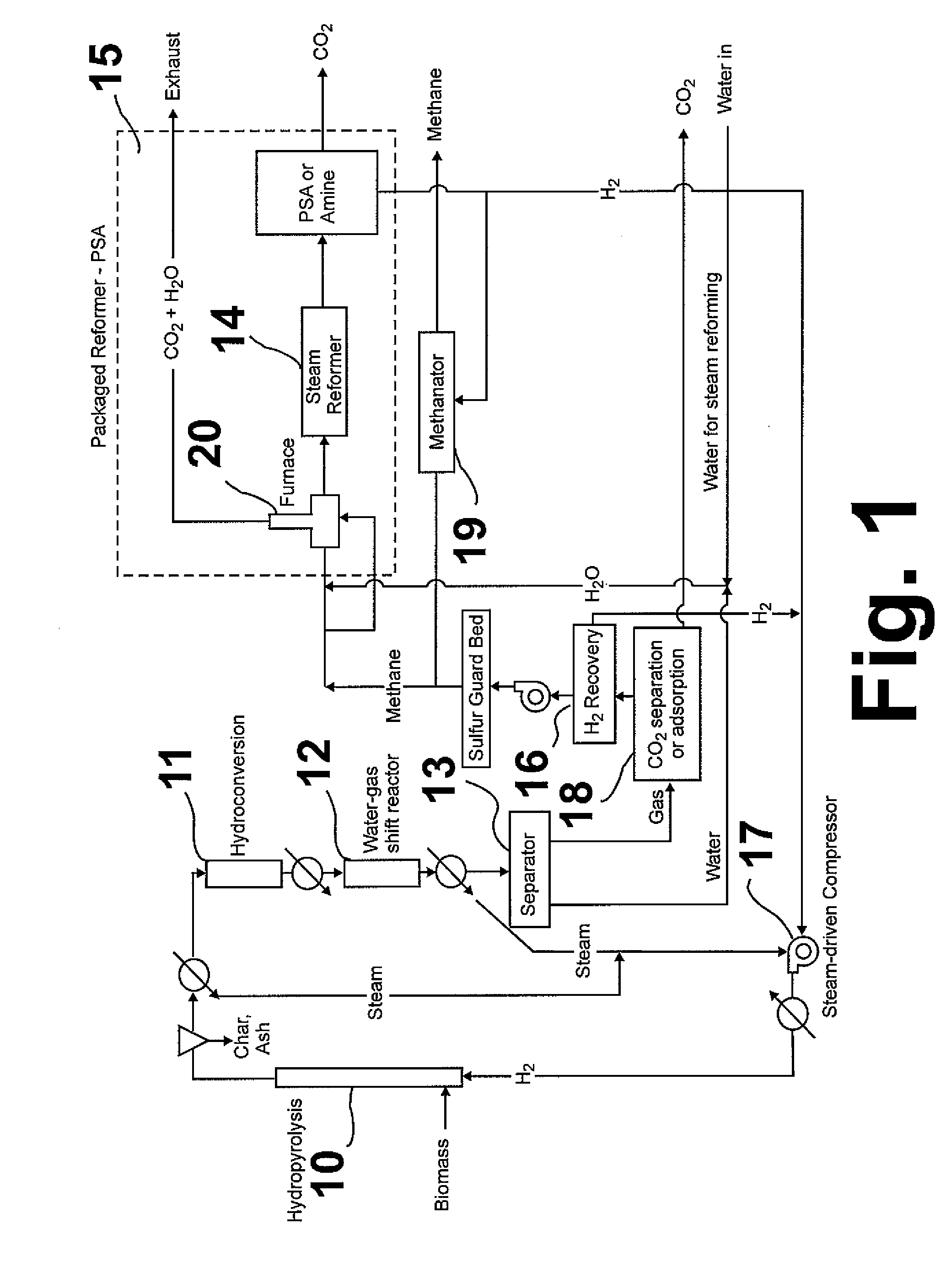
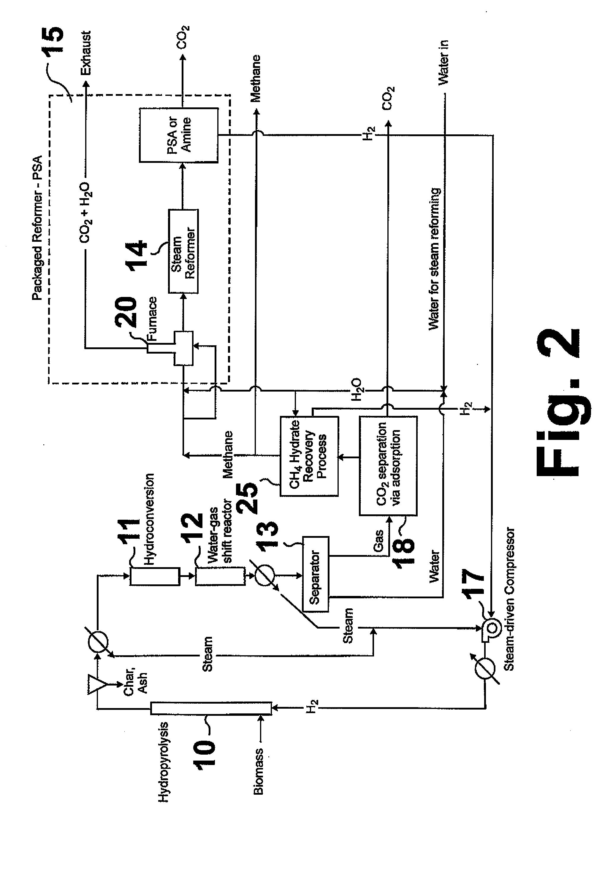
[0014]The process of this invention, shown in FIG. 1, is a compact, integrated, multi-stage process for thermochemically transforming biomass into methane. The first reaction stage or step of this process employs a pressurized, catalytically-enhanced, hydropyrolysis reactor vessel 10 to create a low-char, partially deoxygenated, hydropyrolysis product from which the char is removed. Although any reactor vessel suitable for hydropyrolysis may be employed, the preferred reactor vessel is a fluidized bed reactor. The hydropyrolysis step employs a rapid heat up in which the average internal temperature of the particle rises at a rate of about 10,000° C. / second. The residence time of the pyrolysis vapors in the reactor vessel is less than about 1 minute. In contrast thereto, the residence time of the char is relatively long because it is not removed through the bottom of the reactor vessel and, thus, must be reduced in particle size until the aerodynamic diameter of these particles is su...


PUM

PropertyMeasurementUnit
hydropyrolysis pressureaaaaaaaaaa
hydropyrolysis temperatureaaaaaaaaaa
hydroconversion pressureaaaaaaaaaa

Abstract

A multi-stage method and apparatus for producing methane from biomass in which the biomass is hydropyrolyzed in a reactor vessel containing molecular hydrogen and a deoxygenating catalyst, the output of which is hydrogenated using a hydroconversion catalyst. The output from the hydroconversion step is provided to a water-gas-shift process providing a mixture of H2O and product gases including CO2, H2, and methane. The mixture components are separated, resulting in a product stream comprising substantially only methane.

Description

CROSS-REFERENCE TO RELATED APPLICATION[0001]This application is a continuation-in-part application of our co-pending U.S. patent application Ser. No. 12 / 419,535, filed 7 Apr. 2009.BACKGROUND OF THE INVENTION[0002]1. Field of the Invention[0003]This invention relates to an integrated process for thermochemically transforming biomass directly into methane. As used herein, the term “biomass” refers to biological material derived from living or deceased organisms and includes lignocellulosic materials, such as wood, aquatic materials, such as algae, aquatic plants, seaweed, and animal by-products and wastes, such as offal, fats, and sewage sludge. In one aspect, this invention relates to a multi-stage hydropyrolysis process for producing methane from biomass.[0004]2. Description of Related Art[0005]Conventional pyrolysis of biomass, typically fast pyrolysis, does not utilize or require H2 or catalysts and produces a dense, acidic, reactive liquid product that contains water, oils, and c...

Claims


Application Information

Patent Timeline
Patent Type & Authority Applications(United States)
IPC IPC(8): C10L3/00C10G1/00
CPCC01B3/16B01J37/0201C01B2203/0205C01B2203/0283C01B2203/042C01B2203/043C01B2203/0475C01B2203/0811C01B2203/0827C01B2203/1241C01B2203/1247C01B2203/1258C01B2203/148C10B49/10C10B53/02C10G3/50C10G2300/1011C10J3/463C10L3/08C10L3/102C10L3/103C10L3/104Y02E50/14C10K3/04C10J2300/1662C10J2200/06C10G2300/4018C10K1/024C10K1/026C10G3/42C10G3/46C10G3/57C10G2300/4006C10G2300/4012C10J2300/0916Y02E50/343B01J37/20B01J23/883C01B3/34Y02P20/52Y02P30/20Y02P20/145Y02E50/10Y02E50/30
Inventor MARKER, TERRY L.FELIX, LARRY G.LINCK, MARTIN B.MEYER, HOWARD S.LEPPIN, DENNIS
Owner GAS TECH INST
Learn More