If there is some misalignment, performance may degrade.
Also, the gas flow profile may become more organized before entering the patient's
nostril, rather than a turbulent jet entering the nostril, which would be quite uncomfortable and intolerant to the patient.
Typically the
nozzle may be centered with respect to the manifold internal geometry at the location of the
nozzle; however, it can also be off-center, for example, in situations in which minimal
sound generation is desired.
Unfortunately, without the embodiments described above, the nasal interfaces may generate an undesirable amount of
noise because of the jet pump principle.
Jet pumps are known to create
noise from the gas velocity exiting the jet
nozzle, and the surrounding air being entrained by the jet.
1) Dimensions / Relationshipsa. A jet nozzle
diameter 17201 and distance from a nare opening 17203 may provide that a jet profile 17205 is substantially the same
diameter as the nare 17203 when entering the nare 17203, see FIG. 166.b. The jet nozzle 17201 preferably may be placed concentric to the nare 17203 for maximum performance, although this configuraiton may increase
noise in some situations.
2) Materialsa. A simi-rigid
elastomer may be used for
patient comfort.b. A majority of the sound generated by these configurations may be from the mixing of the
high velocity jet with the low velocity entrained air at the nare opening.
Material selection most likely does not have an affect on sound.
3) Exit Velocitya. Exit velocity perferably is maximized sonic flow to create as large of a
jet flow rate as possible. Limitations may include ventilator source pressure limitations and peak delivered flow requirements.
4) Entrainment / Flow Amplificationa. In these configurations, total flow can be up to four times or more the augmented flow.
5) Pressure Generationa. Values of approximately 17 cmH2O (@0
inspiratory flow) have been observed.
6) Sense Portsa. The sense ports may be as proximal to the nare opening as possible. Preferably the
mask may slightly occlude the nare opening so that a sense port located between the
occlusion and the nare opening may sense the pressure drop due to the
occlusion during an inspiratory effort.
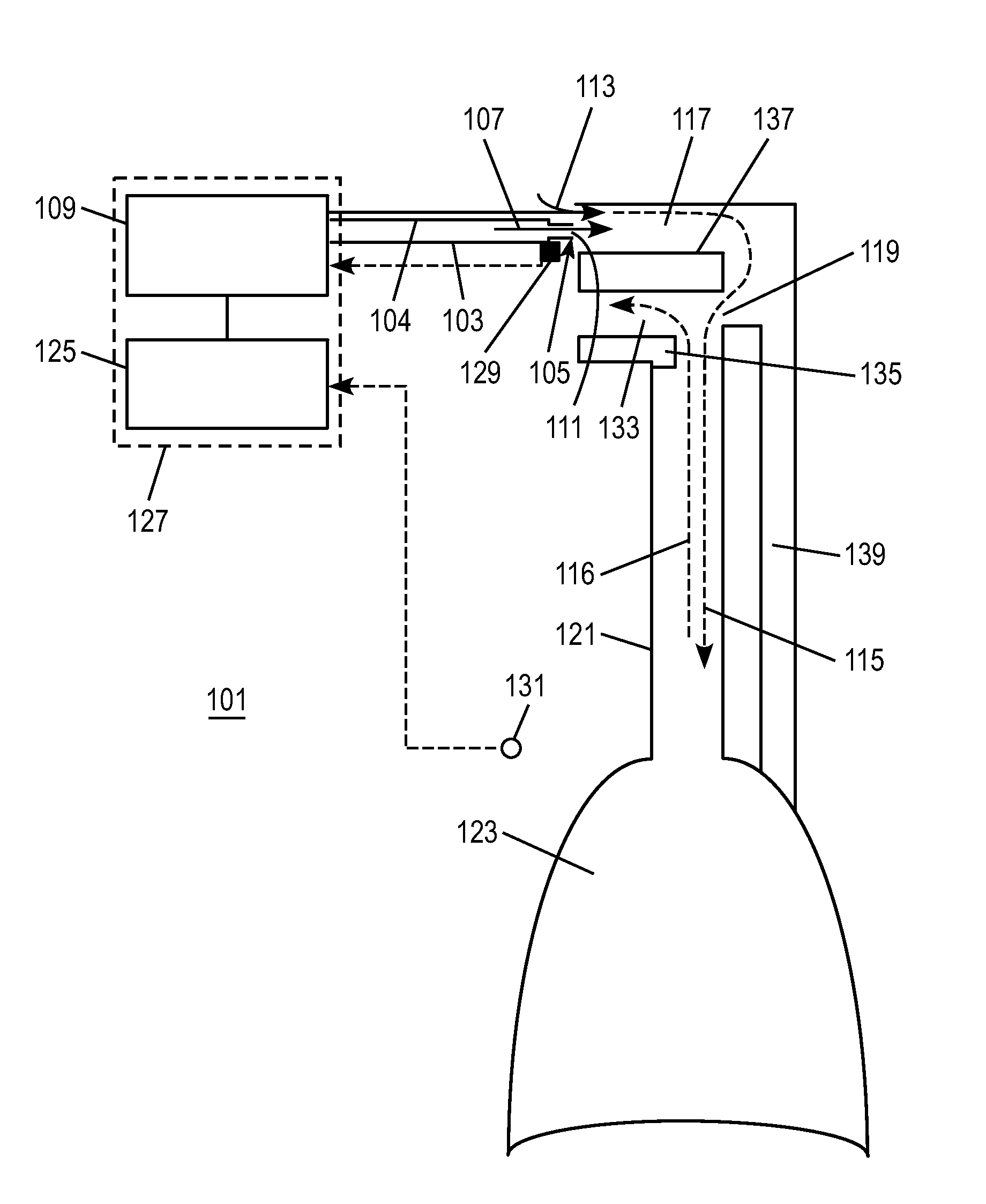
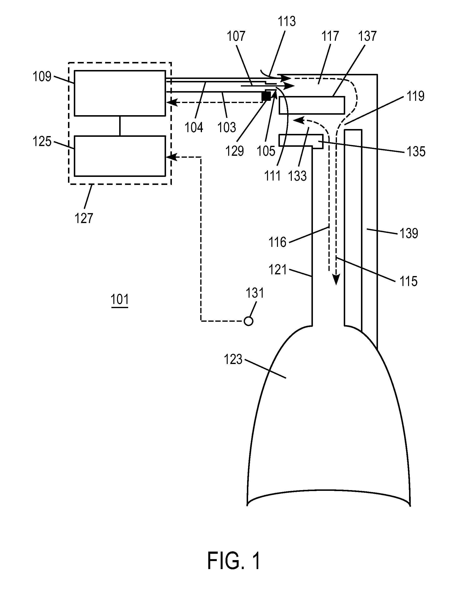
1) Dimensions / Relationshipsa. A jet
diameter 17401 and a distance from the jet to an end of a
throat section 17403 may be configured such that a jet profile 17405 substantially equals the
throat diameter at the entrance to the
throat section, as shown in FIG. 168. Another acceptable extreme may be when a jet diameter 17501 and a distance from the jet to an end of a throat section 17503 may be configured such that a jet profile 17505 is substantially the same diameter as the throat when entering just before exiting the throat section, as shown in FIG. 169.b. Jet may be placed concentric to the throat for maximum performance, although this configuration may be louder than other configurations.c. Jet may be placed near tangent and at a slight angle for maximum noise attinuation without significant reduction in performance.d. The path of the throat section may be fairly straight without significant changes in area and direction. This may apply up to a location where the jet profile area equals the throat diameter. Beyond this critical point the geometry may be more organic.
2) Materialsa. A simi-rigid
elastomer may be used for
patient comfort.b. A simi-rigid
elastomer may also be helpful in attinuating any noise generated in the manifold section of the nasal interface.
3) Exit Velocitya. Exit velocity preferably may be maximized sonic flow to create as large of a
jet flow rate as possible. Limitations to this rule may be ventilator source pressure limitations and peak delivered flow requirements.
4) Entrainment / Flow Amplificationa. In these configurations, total flow can be up to four times the augmented flow.
5) Pressure generationa. Values of 25 cmH2O (@0
inspiratory flow) have been observed, but values of 30 cmH2O or more may be possible.
6) Sense Portsa. The sense ports may be located between the entrainment opening in the
mask and the nasal pillow. The entrainment opening may provide a
differential pressure for the sense ports to measure.b. If the throat section is configured to neck down for increased pressure capacity, then it may be preferable to place the sense port between this
necking and the nasal pillow. This may increase the
differential pressure available for the sense port.
The increase in
tidal volume is considered clinically efficacious, however is technically challenging to achieve in an open ventilation, non-invasive and minimally obtrusive
system.
In the
oxygen therapy walk (top graph), the patient fatigues early and has to stop to rest, because the amount of energy the patient has to expend to breathe to overcome their reduced
lung function, is just too difficult.
Typically, the
heart rate and
blood pressure are extremely elevated in addition to being fatigued, and the CO2 level is high because the patient cannot get enough air in and out, again, because of how much energy is required to breathe.
In the example shown, during the period of partial or complete obstruction, the flow
signal at the nares is not strong enough for the
breathing sensors to detect
respiration.
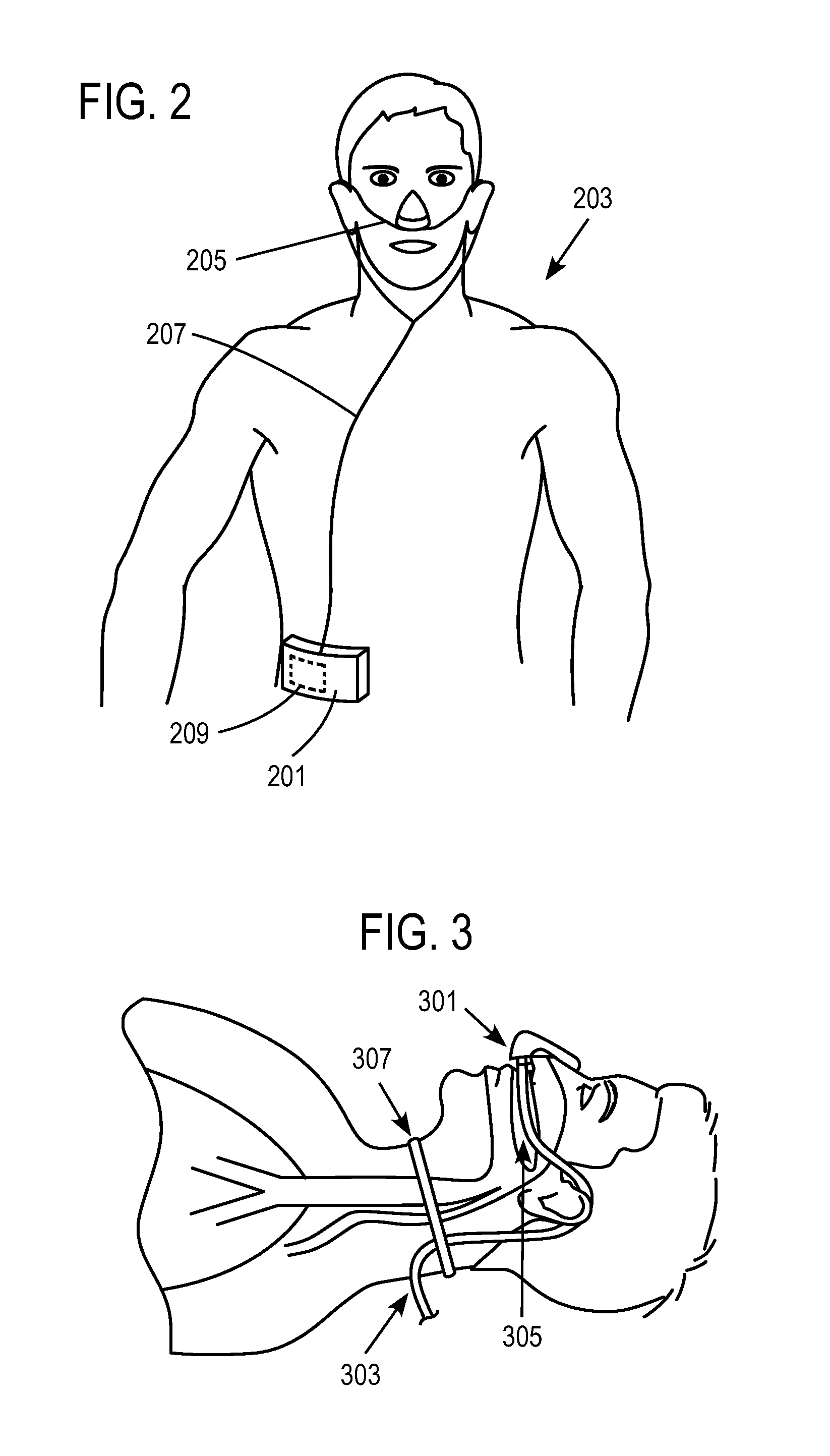
Since the
mask is a completely open mask, this is possible, whereas this is not possible with conventional CPAP and BiPAP
sleep apnea masks and
breathing circuits.
This is difficult and ill advised with conventional PAP therapy in which the patient breathes the significant majority of gas through the mask and hose, in which case it is best to always have the ventilation gas being delivered to the patient to prevent CO2 retention in the hose, mask and airways due to rebreathing.
However, the movement of air in the trachea in response to the breath effort in some cases, depending on the sensor technology being used, may be enough to register as an inspiratory effort and expiratory effort by the sensor.

