
System and method for auto-power gating synthesis for active leakage reduction

a technology of auto-power gating and leakage current, applied in the field of integrated circuit system and method, can solve the problems of increasing power consumption, shortening the operating time, and undesirable increase in power consumption of electronic devices, so as to reduce power consumption, simplify the circuit design and development process, and reduce power consumption.

Active Publication Date: 2010-10-07
TEXAS INSTR INC
View PDF17 Cites 8 Cited by
  • Summary
  • Abstract
  • Description
  • Claims
  • Application Information

AI Technical Summary

Benefits of technology

This approach allows for efficient power control at a fine-grained level, reducing power consumption by powering down unused circuits quickly and transparently, thus enhancing the performance and battery life of electronic devices without complicating the design process.

Problems solved by technology

While integrated circuits typically offer enhanced reliability and lower power consumption over discrete components, the addition of extra integrated circuits usually means that the electronic devices will incur an increase in power consumption.
Increased power consumption may be undesirable, especially for wireless electronic devices, wherein the increased power consumption may shorten the operating time between charges of a battery providing power to a wireless electronic device.
However, a disadvantage of prior art techniques is that they often ignore circuitry that may perform many different functions, which may make it difficult to determine which portions of the circuit to turn on or turn off.
Therefore, a significant portion of circuitry in an electronic device may not have power consumption control.
Another disadvantage of prior art techniques is that they may negatively impact the performance of the circuitry in the electronic device.
Since software may be slow in shutting down or powering up a power domain, the state of circuitry within a power domain may need to be known prior to when the circuitry actually needs to be shut down or powered up.
Yet another disadvantage of prior art techniques is that the power control hardware and software is typically added by designers of the electronic device, which may significantly complicate the design and development process.

Method used


Image

  • System and method for auto-power gating synthesis for active leakage reduction
  • System and method for auto-power gating synthesis for active leakage reduction
  • System and method for auto-power gating synthesis for active leakage reduction

Examples


Embodiment Construction

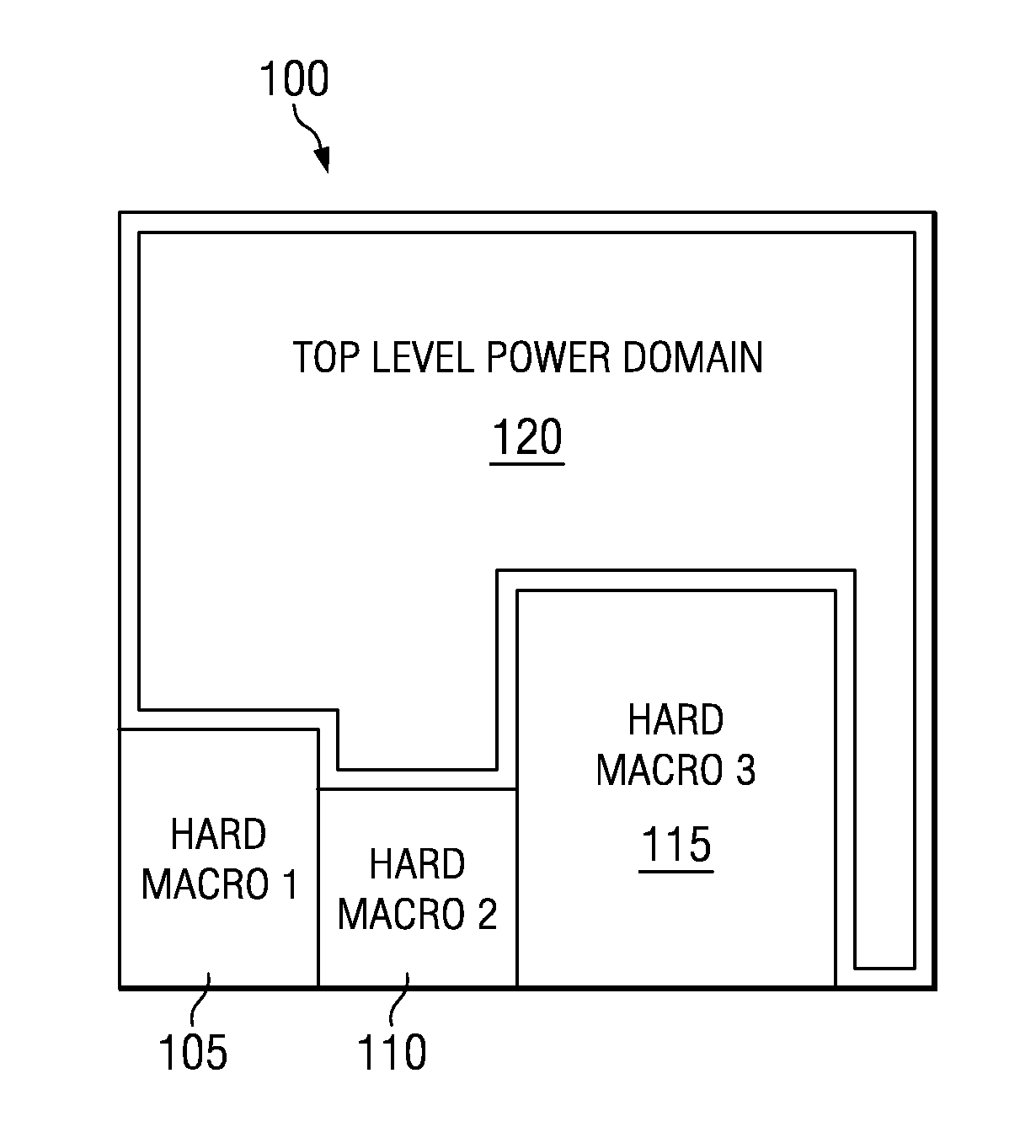
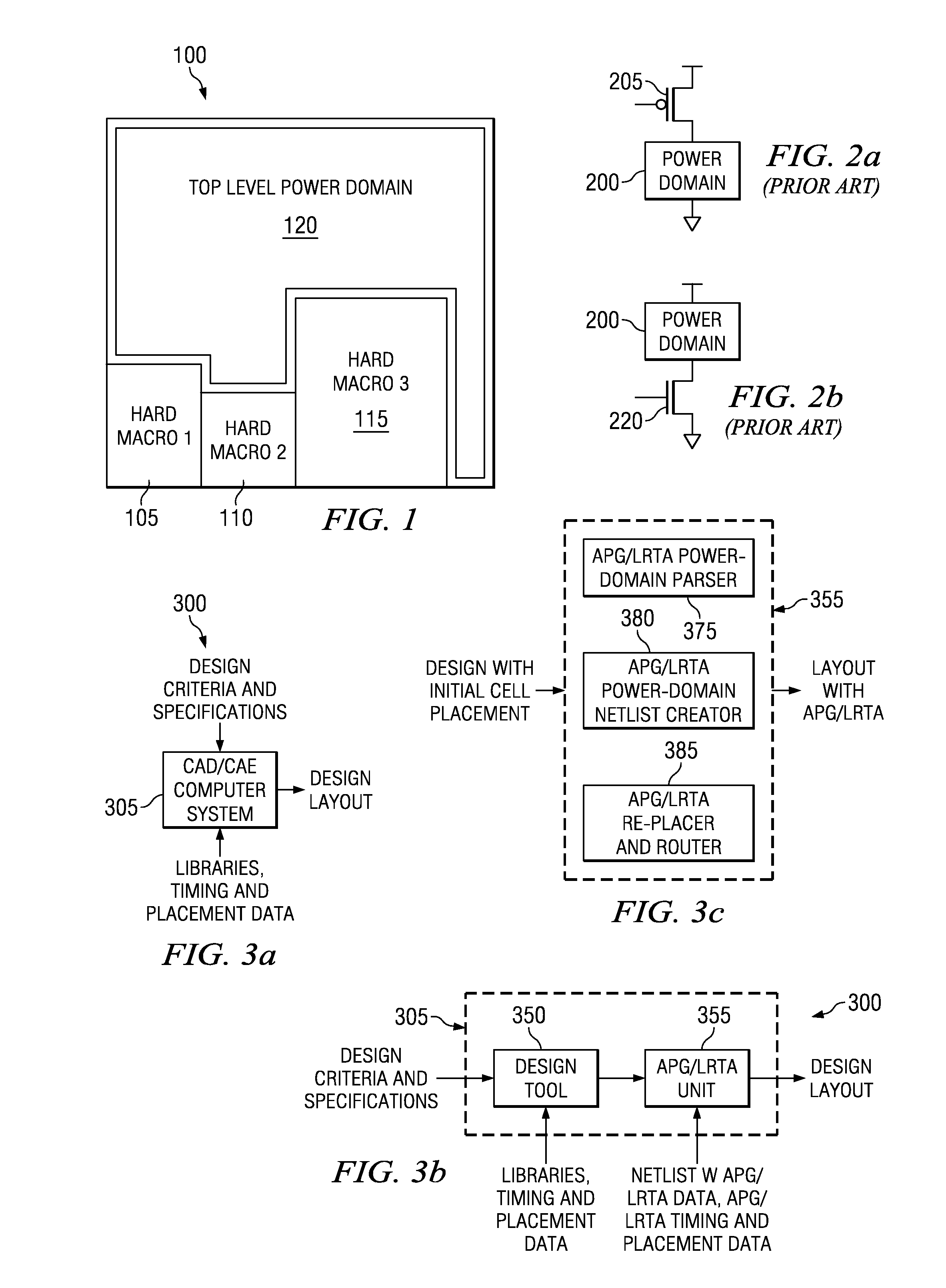
[0031]The making and using of the embodiments are discussed in detail below. It should be appreciated, however, that the present invention provides many applicable inventive concepts that can be embodied in a wide variety of specific contexts. The specific embodiments discussed are merely illustrative of specific ways to make and use the invention, and do not limit the scope of the invention.

[0032]The embodiments will be described in a specific context, namely an integrated circuit containing multiple power domains and a single top level power domain. The invention may also be applied, however, to other integrated circuits containing multiple power domains and multiple top level power domains. Additionally, the invention may also be applied to multiple integrated circuits packaged together, such as in a multi-chip module, a system on a chip, and so forth, into a single electronic device.

[0033]With reference now to FIG. 1, there is shown a diagram illustrating an integrated circuit 1...


PUM


Abstract

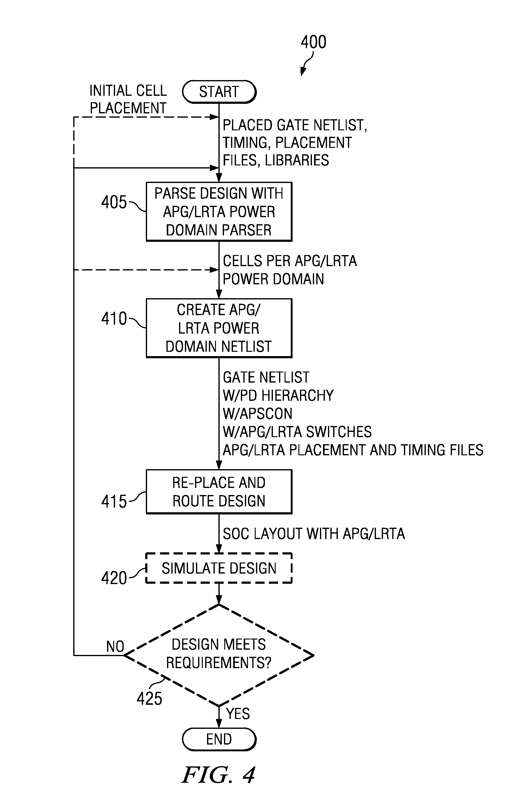
A method includes parsing a design of the integrated circuit to define cells in automatic power gating power domains, automatically creating an automatic power gating power domain netlist from the parsed design of the integrated circuit, and placing and routing the automatic power gating power domain netlist to produce a layout for the integrated circuit. The parsing partitions a high-level power domain of the integrated circuit into one or more automatic power gating power domains. The automatic power gating power domains have substantially zero-cycle power up times, thereby enabling transparent operation. Furthermore, the automatic power gating power domains may be automatically inserted into designs of integrated circuits, thereby relieving integrated circuit designers of the task of inserting power domains and associated hardware and software.

Description

[0001]This application is a divisional and claims the benefit of U.S. Non-provisional application Ser. No. 11 / 947,012, filed on Nov. 29, 2007, which claims the benefit of U.S. Provisional Application No. 60 / 955,230, filed on Aug. 10, 2007, both entitled “Auto-Power Gating Synthesis For Active Leakage Reduction,” which applications are hereby incorporated herein by reference.TECHNICAL FIELD[0002]The present invention relates generally to a system and method for integrated circuits, and more particularly to a system and method for automatic power gating synthesis to reduce active leakage current.BACKGROUND[0003]As electronic devices continue to become more feature rich, the extra functionality typically requires the addition of circuitry to the electronic devices. The additional circuitry being added to the electronic devices usually takes the form of integrated circuits, be it in the form of extra integrated circuits or revisions of existing integrated circuits with more functional p...

Claims


Application Information

Patent Timeline
Patent Type & Authority Applications(United States)
IPC IPC(8): G05F1/10G06F17/50
CPCG06F2217/78G06F17/5045G06F30/30G06F2119/06
Inventor WANG, ALICEMAIR, HUGH T.GAMMIE, GORDONKO, UMING
Owner TEXAS INSTR INC
Learn More