
Dynamic Bandwidth Allocation Method of Ethernet Passive Optical Network

a bandwidth allocation and dynamic technology, applied in the field of dynamic bandwidth allocation of an can solve the problems of inability to handle the varying data packet demands of onus, low bandwidth utilization rate, inacceptable voice or real-time video traffic, etc., to achieve accurate prediction, improve the bandwidth utilization rate of the ethernet passive optical network, and fast convergence

Inactive Publication Date: 2010-10-07
CHUNGHWA TELECOM CO LTD
View PDF2 Cites 68 Cited by
  • Summary
  • Abstract
  • Description
  • Claims
  • Application Information

AI Technical Summary

Benefits of technology

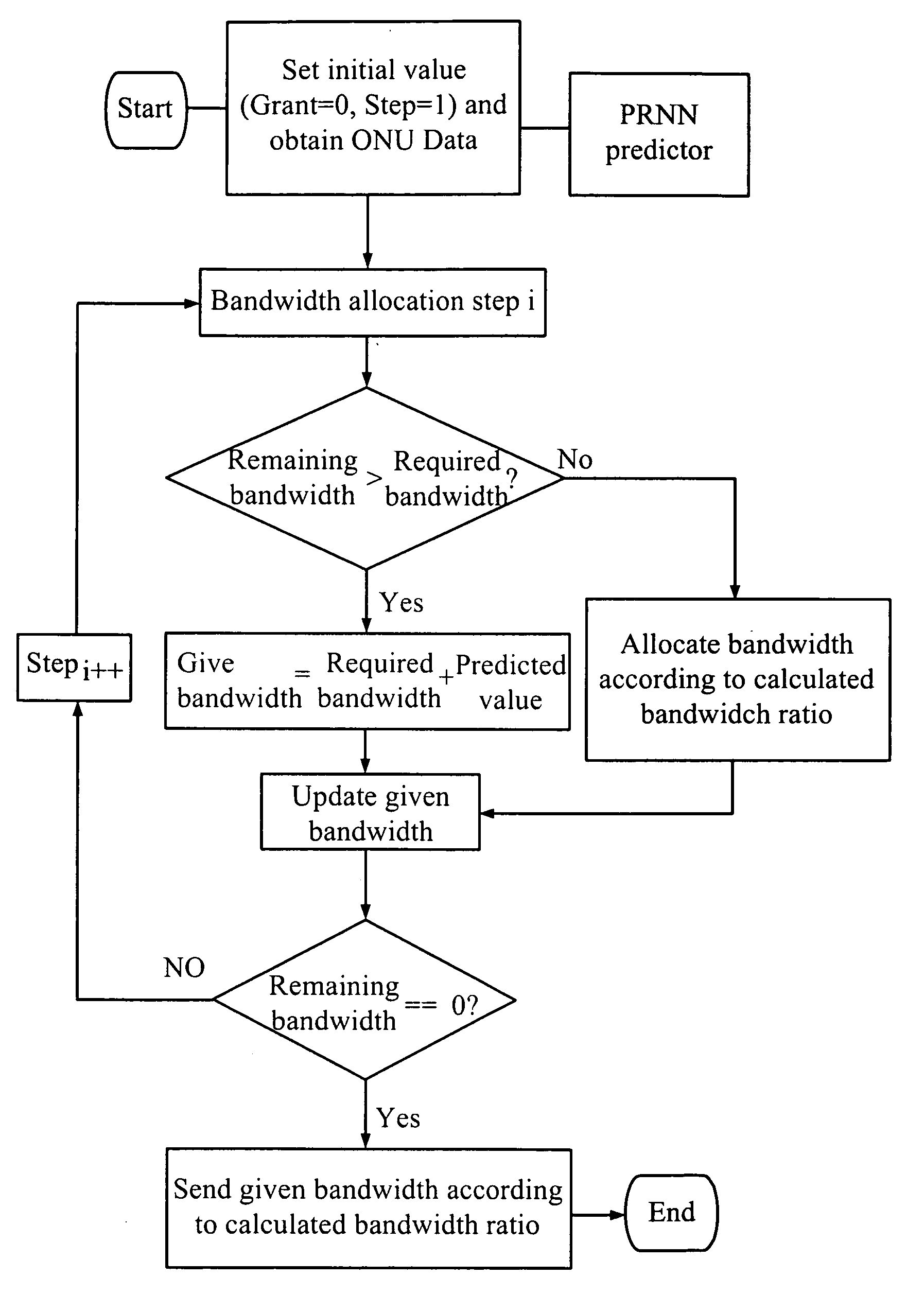
[0009]It is an object of the present invention to provide a dynamic bandwidth allocation method of an Ethernet passive optical network, wherein the method predicts a client behavior and numbers of various kinds of packets by using a pipeline scheduling predictor consisted of a pipelined recurrent neural network (PRNN), and a learning rule of the extended recursive least squares (ERLS), since the PRNN predictor is advantageous in providing fast convergence and accurate prediction, it is suitable for making prediction of the Ethernet passive optical network, wherein each ONU uses a pig-tail mechanism for late-reported traffic type. Therefore, the predictor improves the bandwidth utilization rate of the Ethernet passive optical network.
[0010]It is another object of the present invention to provide a dynamic bandwidth allocation method of an Ethernet passive optical network, wherein the method proposes a rule of QoS-promoted Dynamic Bandwidth Allocation (PQ-DBA) to improve the uplink / downlink algorithm of the Interleaved Polling with Adaptive Cycle Time (IPACT) for the Ethernet passive optical network, as defined in IEEE 802.3ah, and to overcome the deficiencies of other DBA methods in terms of QoS and client behavior predictions to maximize the bandwidth utilization. Besides, the PQ-DBA method can also improves the average data delay time and fairness for priority-based packets.
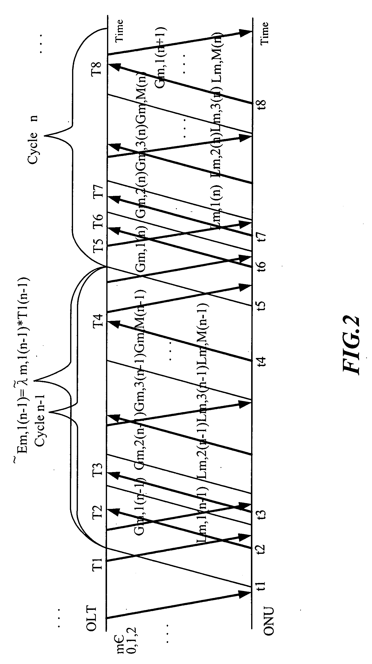
[0020]It will take two to three cycle times for the OLT and the ONU uses GRANT and REPORT MPCPDU to communicate with each other, while during the cycle times the client of the ONU could be still transmitting data. Therefore, the present invention uses the PRNN predictor to estimate transmission rates of various kinds of packets of the ONU for each cycle time, and to multiply the transmission rates with the cycle time to estimate a number of new packets for each service (recorded in L0,i, L1,i, L2,i, Ldp,i, Ld,i, Lw,i) as a reference for the OLT in distributing the bandwidth for each ONU, thereby improving the utilization rate of the Ethernet passive optical network.

Problems solved by technology

Although TDMA is easy to implement in EPON, it can't handle the varying data packet demands of ONUs and has a low bandwidth utilization rate.
According to the rule of IPACT, packets from the ONU are processed in a First Come First Serve (FCFS) manner, so each packet would have a fixed delay time, which is not acceptable for voice or real-time video traffic since it could cause higher jitter.
Many studies have been proposed to improve QoS, such as the DBA-High Priority cited in reference [3], which reduces the delay time and the jitter of high-priority services but also increases the drop probability and the delay time of low-priority services and thus results in lower throughput for low-priority services.
Furthermore, an intra-ONU, inter-ONU, two layer bandwidth allocation (TLBA) method has proposed to increase the cycle time of each ONU to solve the unfairness in dealing with high- and low-priority services as recited in reference [3]; however, it increases the delay time and reduces the throughput of high-priority services and fails to meet the demands of burst traffic.
The burst-polling based delta DBA method (reference[6]) and the DBA with multiple service (DBAM) method (reference[7]) are proposed to improve the average delay time by predicting the arriving packets, however, the maximum window mechanism proposed in both references is designed to let the OLT give more bandwidth than that required by the ONU and tends to waste valuable bandwidth and reduces transmission performance.

Method used


Image

  • Dynamic Bandwidth Allocation Method of Ethernet Passive Optical Network
  • Dynamic Bandwidth Allocation Method of Ethernet Passive Optical Network
  • Dynamic Bandwidth Allocation Method of Ethernet Passive Optical Network

Examples


Embodiment Construction

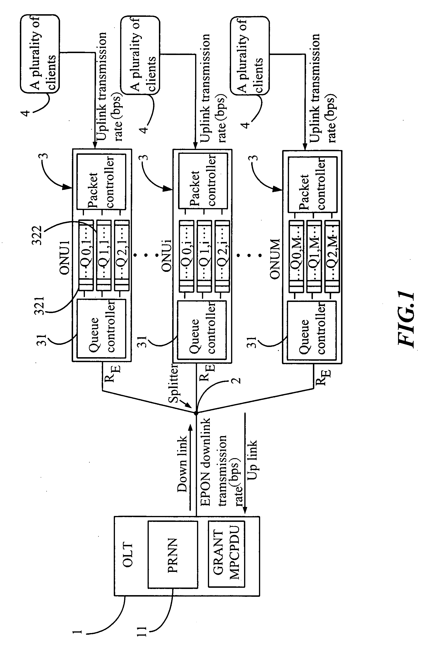
[0027]Please refer to FIG. 1 for a system structure of an Ethernet passive optical network using a dynamic bandwidth allocation method, which comprises:

[0028]a optical line terminal (OLT) 1 coupling with a splitter 2 for broadcasting downlink packets to a plurality of optical network units (ONU) 3, the OLT 1 further comprising a pipelined recurrent neural network (PRNN) 11 for distributing a GRANT MultiPoint Control Protocol Data Unit (MPCPDU);

[0029]the splitter 2 coupling with the OLT 1 and the plurality of ONUs 3, wherein the splitter 2 is a one-to-multiple-point splitter;

[0030]the plurality of ONUs 3 coupling with the splitter 2 and a plurality of clients 4, each ONU receiving its own packets according to a Logic Link Identifier (LLD) and dropping packets not matching with its LLD; each ONU comprising a queue controller 31, a voice packet queue 321, a video packet queue 322, a data packet queue 323 and a packet controller 33. Besides, the plurality of ONUs 3 would add a REPORT MP...


PUM


Abstract

A dynamic bandwidth allocation method of an Ethernet passive optical network, comprises a predictor and a rule of QoS-promoted dynamic bandwidth allocation (PQ-DBA); the predictor predicts a client behavior and numbers of various kinds of packets by using a pipeline scheduling predictor consisted of a pipelined recurrent neural network (PRNN), and a learning rule of the extended recursive least squares (ERLS); the present invention establishes a better QoS traffic management for the OLT-allocated ONU bandwidth and client packets sent by priority.

Description

BACKGROUND OF THE INVENTION[0001]1. Field of the invention[0002]The present invention relates to a dynamic bandwidth allocation (DBA) method of an Ethernet passive optical network (EPON), and more particularly, to a DBA method which is based on a pipeline scheduling predictor consisted of a pipelined recurrent neural network (PRNN) and a learning rule of the extended recursive least squares (ERLS) to predict a client behavior and numbers of various kinds of packets for new arriving packets of each optical network unit (ONU) in a cycle time to provide a reference for a optical line terminal (OLT) in granting bandwidth allocation, thereby increasing the transmission performance between the OLT and the ONU while reducing a packet loss rate of the ONU.[0003]2. Description of the Prior Art[0004]There have been studies of the scheduling of uplink signals in an Ethernet passive optical network (EPON). Since the uplink bandwidth of EPON is shared between ONUs, it is vital to allocate the up...

Claims


Application Information

Patent Timeline
IPC IPC(8): H04B10/20H04J3/22H04J14/08
CPCH04L47/10H04L47/24H04Q2011/0064H04Q11/0067H04L47/32
Inventor PENG, JAN-WENWU, HSING-YICHANG, CHUNG-JU
Owner CHUNGHWA TELECOM CO LTD
Learn More