Method and apparatus for atomic layer deposition using an atmospheric pressure glow discharge plasma

a glow discharge plasma and atomic layer technology, applied in the field of methods, can solve problems such as inconvenient deposition of materials on temperature sensitive substrates

Inactive Publication Date: 2010-10-07
FUJIFILM MFG EURO
View PDF21 Cites 398 Cited by
  • Summary
  • Abstract
  • Description
  • Claims
  • Application Information

AI Technical Summary

Benefits of technology

[0045]In a further embodiment, the plasma generator is arranged to generate a pulsed atmospheric pressure glow discharge plasma. The plasma generat...

Problems solved by technology

), are not suitable for deposition of material on te...

Method used


Image

  • Method and apparatus for atomic layer deposition using an atmospheric pressure glow discharge plasma
  • Method and apparatus for atomic layer deposition using an atmospheric pressure glow discharge plasma
  • Method and apparatus for atomic layer deposition using an atmospheric pressure glow discharge plasma

Examples


example 1

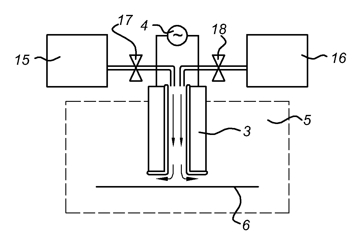
[0110]A sheet prepared with OLED device (substrate 6) was mounted in an experimental set-up as shown in FIG. 8. The complete set-up was placed in a glove box (type Mbraun Labmaster 130) which is purged with pure nitrogen gas. The rotation speed of the drum was set to 15 m / min and the number of rotations was set to 100 cycles.

[0111]Step A: A short “direct” plasma step (i.e. the substrate is moved through the electrodes of the plasma) is carried out to form a uniform NH2-terminated surface layer.

[0112]Step B: SiH2Cl2 precursor and nitrogen gas are supplied to the surface of the substrate 6. Due to atmospheric pressure SiH2Cl2 is reacting very quickly with the amine (NH2) groups. Typical concentration of SiH2Cl2 is 200 mg / hr. Then a purge step is performed using nitrogen.

[0113]Step C: After flushing the gap to remove the abundant precursor the ammonia is inserted as reactive agent in a concentration of 1% in inert nitrogen. Subsequently the direct atmospheric (glow) discharge plasma is...

example 2

[0116]Again a sheet is prepared comprising of OLED devices which was mounted in the experimental set-up as shown in FIG. 8. In this set-up the direct atmospheric pressure plasma unit is replaced by a remote plasma generator using an electrode arrangement of the type shown in FIG. 5a.

[0117]Step A: A short remote plasma step is carried out to form a uniform —NH2 terminated surface layer.

[0118]Step B: of the SiH2Cl2 precursor and nitrogen gas are supplied to the surface. Due to atmospheric pressure SiH2Cl2 is reacting very quickly with the amine (NH2) groups. Typical concentration of SiH2Cl2 is 200 mg / hr. Then a purge step is performed using nitrogen.

[0119]Step C: After flushing the gap to remove the abundant precursor the ammonia is inserted in a concentration of 1% in nitrogen. Subsequently the remote atmospheric discharge plasma is ignited to convert the surface substrate 6 again to an uniform NH2-terminated surface layer. This is illustrated in the table below for an example with ...

example 3

[0122]In a further embodiment the remote plasma generator using the electrode arrangement of the type shown in FIG. 5a is replaced by the type of FIG. 5b.

[0123]Step A: A short plasma step is carried out to form a uniform NH2 terminated surface layer.

[0124]Step B: of the SiH2Cl2 precursor and nitrogen gas are supplied to the surface. Due to atmospheric pressure SiH2Cl2 is reacting very quickly with the amine (NH2) groups. Typical concentration of SiH2Cl2 is 200 mg / hr.

[0125]Step C: After flushing the gap to remove the abundant precursor the ammonia is inserted in a concentration of 1% in nitrogen. Subsequently the direct (stabilized) atmospheric discharge plasma is ignited to convert the surface substrate 6 again to an uniform NH2-terminated surface layer. This is illustrated in the table below for an example with a cycle time of 2 seconds.

“Remote”Station#Gas compositiontreatment timePlasma1) Nitrogen + SiH2Cl210 slm + 200 mg / hr0.5Off2) Nitrogen10 slm0.5Off3) Nitrogen +10 slm + 0.1 s...


PUM

PropertyMeasurementUnit
Fractionaaaaaaaaaa
Fractionaaaaaaaaaa
Fractionaaaaaaaaaa

Abstract

Apparatus and method for atomic layer deposition on a surface of a substrate (6) in a treatment space. A gas supply device (15, 16) is present for providing various gas mixtures to the treatment space (1, 2). The gas supply device (15, 16) is arranged to provide a gas mixture with a precursor material to the treatment space for allowing reactive surface sites to react with precursor material molecules to give a surface covered by a monolayer of precursor molecules attached via the reactive sites to the surface of the substrate. Subsequently, a gas mixture comprising a reactive agent capable to convert the attached precursor molecules to active precursor sites is provided. A plasma generator (10) is present for generating an atmospheric pressure plasma in the gas mixture comprising the reactive agent, the plasma generator being arranged remote from the treatment space (1, 2).

Description

FIELD OF THE INVENTION[0001]The present invention relates to a method for atomic layer deposition on the surface of a substrate. In a further aspect, the present invention relates to an apparatus for atomic layer deposition on the surface of a substrate including an atmospheric plasma system. In an even further aspect of this invention, the apparatus is used for the deposition of a chemical substance or element.PRIOR ART[0002]Atomic layer deposition (ALD) is used in the art to provide layers of a material on the surface of a substrate. Different from chemical vapor deposition (CVD) and physical vapor deposition (PVD), atomic layer deposition (ALD) is based on saturated surface reactions. The intrinsic surface control mechanism of ALD process is based on the saturation of an individual, sequentially-performed surface reaction between the substrate reactive sites and precursor molecules. The saturation mechanism makes the film growth rate directly proportional to the number of reactio...

Claims


Application Information

Patent Timeline
IPC IPC(8): H01L31/18C23C16/448C23C16/00
CPCC23C16/0245C23C16/4554C23C16/452
Inventor DE VRIES, HINDRIK WILLEM
Owner FUJIFILM MFG EURO
Why Eureka
Try Eureka