[0027]As results of the present invention, in a surface treating method of the present invention, which generates a sucking
cavitation flow containing cavitation bubbles, by sucking in fluid via a narrowed portion provided at
midstream of a flow passage, and which acts a crushing
impact force of the cavitation bubbles on a treated surface in the vicinity of the narrowed portion, into the sucking
cavitation flow, a fluid suction passage communicating with a
fluid supply passage via only the narrowed portion is provided, so as to approximately concentrically surround the periphery of the fluid supply passage having the narrowed portion at one end thereof, and the sucking
cavitation flow is generated at the direct downstream of the narrowed portion, by sucking the fluid into the fluid suction passage using a suction means, as well as a surface treating is performed on the treated surface, by crushing the sucking cavitation flow approximately perpendicular to the treated surface. Accordingly, the flow condition of the fluid near the narrowed portion is not greatly varied depending on the circumferential position of the cross section of the narrowed portion, the stable sucking cavitation flow can be generated at the direct downstream of the narrowed portion, so that the even surface treating can be performed over the whole treated surface, and the stable surface treating can be performed for a large treated material, so as to be able to improve a
processing accuracy and to enlarge the treating size. Because the sucking cavitation flow is crushed approximately perpendicular to the treated surface, whereby the cavitation bubbles into the sucking cavitation flow can be approached at least near the treated surface, and the crushing impact force of the cavitation bubbles can be significantly acted on the treated surface, so as to enhancing a processing efficiency.
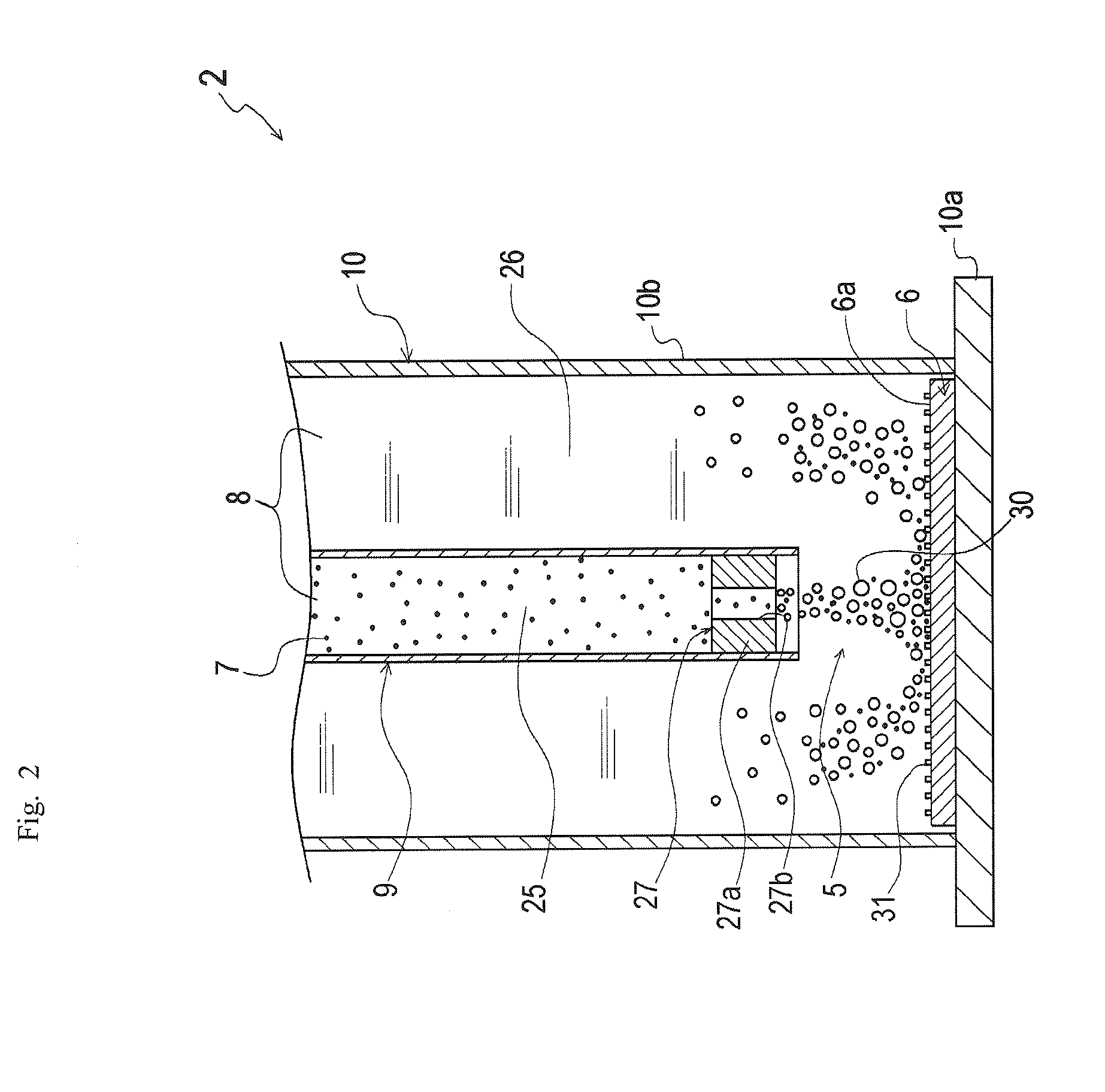
[0028]The surface treating method of the present invention crushes
particulates approximately perpendicular to the treated surface, by distributing and mixing the
particulates with the fluid and by acting the
particulates on the crushing impact force of the cavitation bubbles. Accordingly, the colliding force that the treated surface received from the particulates increases, a vortex due to the
water flow flown out of the narrowed portion and the reversed flow thereof is generated, near the treated surface at which the flow direction of the fluid widely varies, and the particulates remain at a stagnation caused into the vortex, so that the number of the particulates receiving the crushing impact force increases, so as to fully strength the colliding force by the particulates and to further improve the processing efficiency.
[0029]The fluid into the fluid suction passage is sucked using the suction means, and the fluid into the fluid supply passage is pressurized and sent using a pressure feeding means, thereby being able to crush the sucking cavitation flow more intensively onto the treated surface, so as to enhance the surface treating speed and the processing speed.
[0030]The narrowed portion is opened, after sucking the fluid into the fluid supply passage using the suction means and increasing an inner pressure in the fluid supply passage than an inner pressure in the fluid suction passage, with the narrowed portion preliminarily closed, thereby being able to crush the
high pressure sucking cavitation flow onto the treated surface, so as to enhance the surface treating speed and the processing speed.
[0031]The temperature of the fluid is controlled at the given temperature, thereby being able to control the temperature to the temperature state easy to generate the cavitation bubbles and to increase the cavitation bubbles, so as to improve the surface treating efficiency.
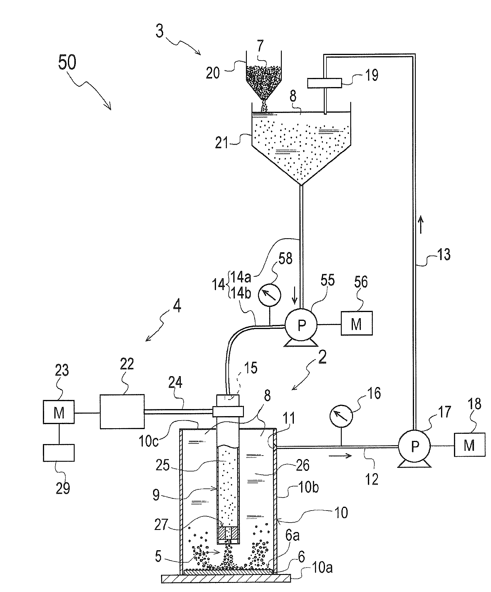
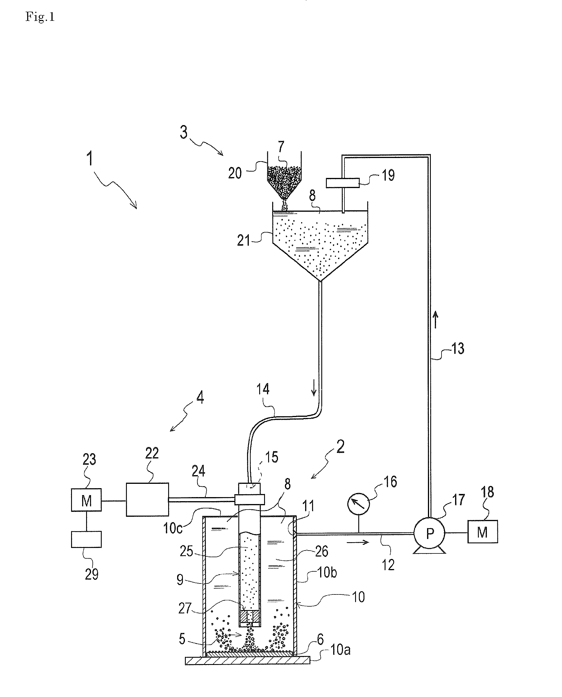
[0032]In a surface treating device, comprising a narrowed portion at
midstream of a flow passage for a fluid, which is equipped with a construction that generates a sucking cavitation flow containing cavitation bubbles, by sucking the fluid via the narrowed portion and acts a crushing impact force of the cavitation bubbles on a treated surface in the vicinity of the narrowed portion in the sucking cavitation flow, the surface treating device comprises a fluid supply passage, which has the narrowed portion at one end thereof and which can supply the fluid with the narrowed portion, a fluid suction passage communicating with the fluid supply passage via only the narrowed portion, and a suction means which sucks the fluid into the fluid suction passage, wherein the fluid suction passage approximately concentrically surrounds the periphery of the fluid supply passage, and wherein the narrowed portion is arranged opposite to the treated surface. Accordingly, the flow condition of the fluid near the narrowed portion is not greatly varied depending on the circumferential position of the cross section of the narrowed portion, the stable sucking cavitation flow can be generated at the direct downstream of the narrowed portion, so that the even surface treating can be performed over the whole treated surface, and the stable surface treating can be performed for a large treated material, so as to be able to improve a
processing accuracy and to enlarge the treating size. Because the sucking cavitation flow is crushed approximately perpendicular to the treated surface, whereby the cavitation bubbles into the sucking cavitation flow can be approached at least near the treated surface, and the crushing impact force of the cavitation bubbles can be significantly acted on the treated surface, so as to enhancing a processing efficiency. The above-mentioned effects can be achieved, only by providing the simple construction that the narrowed portion is arranged opposite to the treated surface.

