Light Emitting Device and Fabrication Thereof

Inactive Publication Date: 2010-10-14
CHUNG YUAN CHRISTIAN UNIVERSITY
View PDF5 Cites 17 Cited by
  • Summary
  • Abstract
  • Description
  • Claims
  • Application Information

AI Technical Summary

Benefits of technology

[0008]One object of the present invention is to provide a light emitting diode so as to achieve industrial demands and improve above issues caused by conventional LEDs.
[0010]The present invention increased light extraction efficiency by the mesh substrate. The mesh substrate comprises a mesh layer and a metallic capping layer. The mesh layer is made of transparent medium such as Si, LaAlO3, LiGaO2, GaN, SiC, sapphire (Al2O3) or diamond and with a plurality of cavities spread on the bottom by digging. The metallic capping layer is under the mesh layer. The plurality of cavities is covered by the metallic capping layer with high reflective metal such as silver (Ag) or aluminum (Al) in order to generate mirror reflection effect on the mesh substrate.
[0013]The light emitting diode produced by above fabrication has a mesh substrate with a mesh texture structure thereby generate multiple-reflection to increase luminous brightness. In addition, the thermal dissipation layer disposed under the mesh substrate by means of coating or electroplating. Because metal with high thermal conductivity is used in the thermal dissipation layer, the heat that generated by photoelectric effect can be appropriately dissipated and the internal junction temperature can be decreased. Therefore, the emitting efficiency and lifetime of the LED are both increased.
[0014]The present invention via LASER scribing method is used to build up a texture on the backside of the sapphire substrate. High reflectivity and thermal conductivity metals are thereafter deposited or coated onto the mesh substrate to enhance the emitting efficiency. Meanwhile, junction temperature will be decreased and thermal effect, a negative effect to light emitting diode, will be eased.

Problems solved by technology
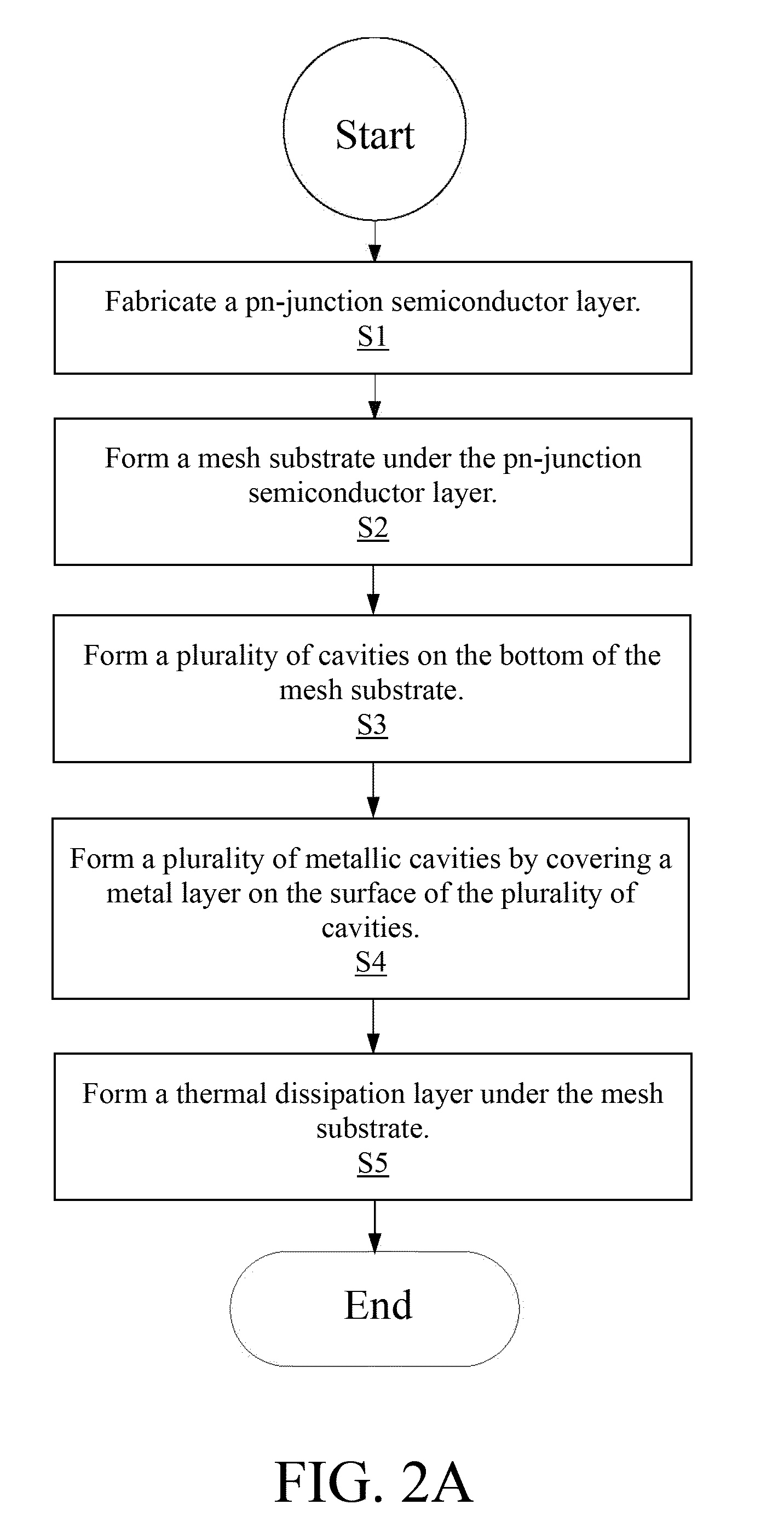
Besides improving light characteristic and epitaxial quality, decreasing the temperature of quantum well region is also an important issue.
Therefore, decrease the temperature of quantum well can prolong the LED lifetime and avoid the thermal effect to reduce light efficiency.
), the sapphire substrate can not appropriately dissipate heat that generated by photoelectric effect.
Over-high temperature in lighting region of LED can reduce its emitting efficiency and lifetime.

Method used


Image

  • Light Emitting Device and Fabrication Thereof
  • Light Emitting Device and Fabrication Thereof
  • Light Emitting Device and Fabrication Thereof

Examples


Embodiment Construction

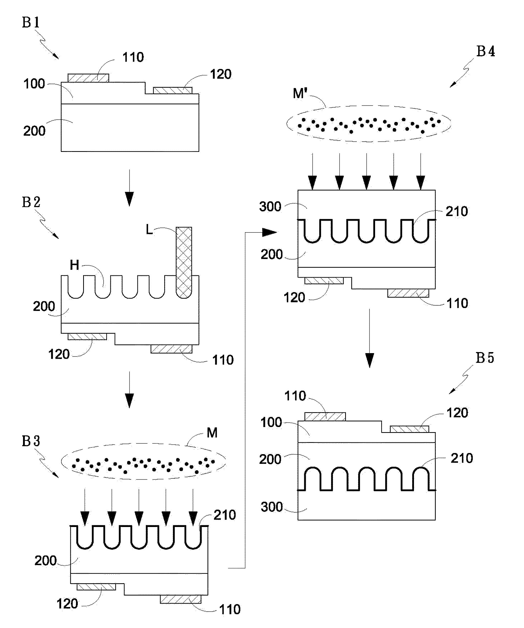
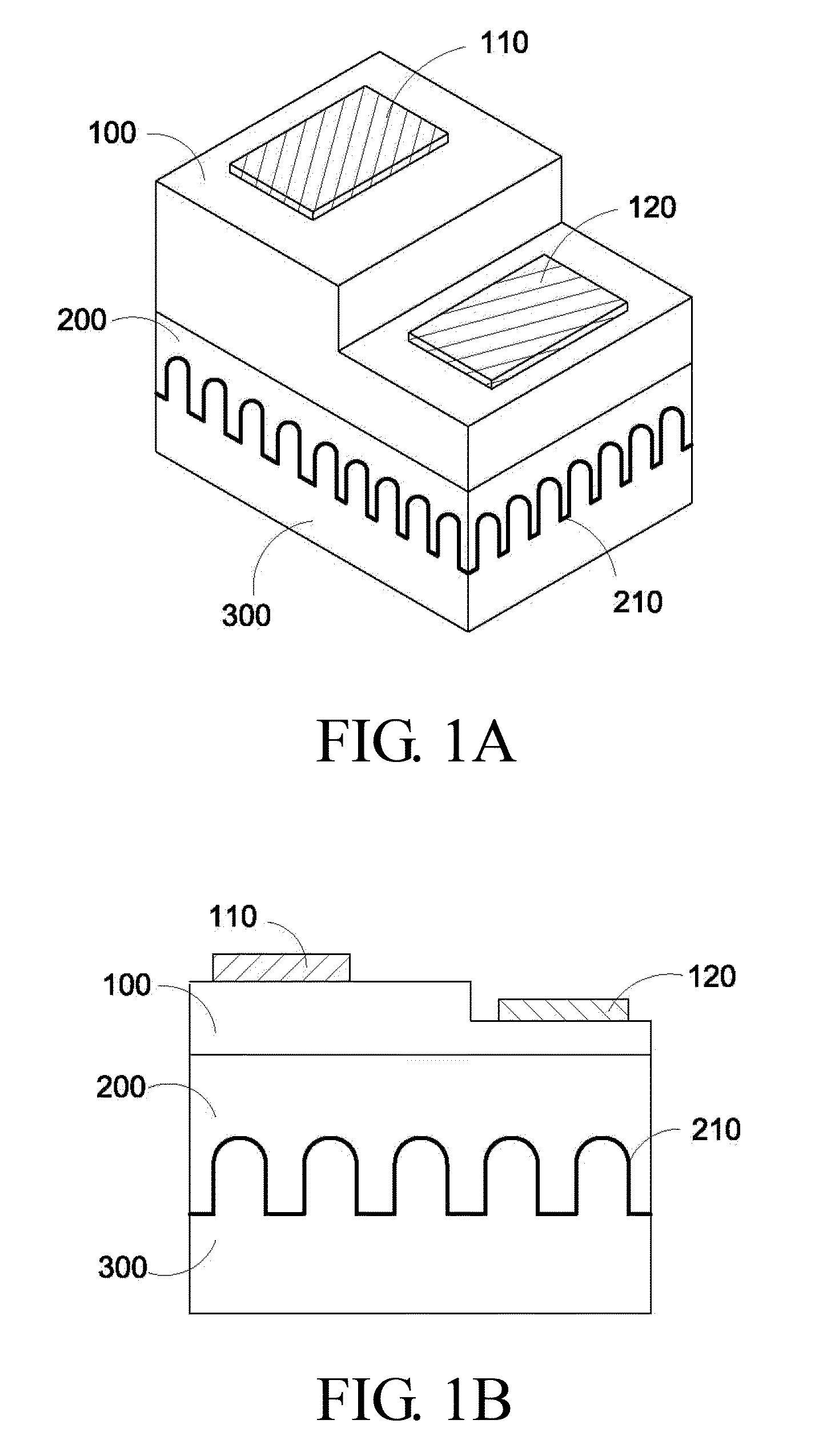
[0021]The present invention hereby discloses a light emitting diode and fabrication thereof. To thoughtfully understand the present invention for the readers, it will be described in detail below what the procedures and the components. Obviously, practice of the present invention does not to be place restrictions on the light emitting diode and fabrication thereof that those of ordinary skill in the art can understand the partial detail. On the other hand, the procedures or the components which are known to all do not be specified in this application, to avoid causing not necessary limitation on the present invention. Best model of the present invention will be specified below, however except those detailed descriptions, the present invention also can be use widely within other embodiments, otherwise scope of the present invention does not be restricted, and it will be principle to below claims.

[0022]The present invention is fabricated after manufacturing a conventional horizontal t...


PUM


Abstract

A light emitting diode of the invention via laser scribing method is used to build up the mesh texture on the backside of the sapphire of light emitting diodes. Then high reflectivity and thermal conductivity metals are deposited onto the mesh structure. Since the multiple-reflection from the texture, the light extraction efficiency will be increased. Meanwhile, the high thermal conductivity metal filled into the sapphire also lead to the better heat dissipation within the light emitting diodes, it will decrease the junction temperature and avoid the thermal effect to reduce light efficiency and the lifetime.

Description

BACKGROUND OF THE INVENTION[0001]1. Field of the Invention[0002]The present invention relates a fabrication of light emitting diode to enhance the brightness and increase the lifetime.[0003]2. Description of the Related Art[0004]The conventional light emitting diode (LED) comprises a semiconductor substrate, an illumination structure on the semiconductor substrate and two ohmic contact electrodes. The illumination structure generally is formed by multilayered Group III-V compound semiconductor layer containing aluminum. For example, AlGaAs can emit infrared light and red light, or AlGaInP can emit yellow-green light, yellow light and red light. Presently, the worldwide industry has developed several kinds of LED with different wavelengths from infrared to blue. There are also LEDs with wavelengths from purple to ultraviolet. In recently years, the most attractive development is coating the light emitting diode with phosphor that converts blue light to white light.[0005]Most white LE...

Claims


Application Information

Patent Timeline
IPC IPC(8): H01L33/32H01L33/64
CPCH01L21/268H01L33/20H01L33/642H01L33/641H01L33/46
Inventor LEE, YEEU-CHANGLEE, KO-TAO
Owner CHUNG YUAN CHRISTIAN UNIVERSITY
Why Eureka
Try Eureka