Apparatus and system for a quasi longitudinal mode electro optic sensor for high power microwave testing

a quasi-longitudinal mode, electro-optical sensor technology, applied in the direction of optical radiation measurement, instruments, measurement devices, etc., can solve the problems of unacceptably large field perturbations, unfavorable eo signal stability, and inability of d-dot sensor to accurately measure the true field, etc., to reduce the perturbation to the electrical field, improve the stability of eo signal, and improve the effect of optical coupling

Active Publication Date: 2010-10-21
US GOVT REPRESENTED BY SEC OF NAVY CHIEF OF NAVAL RES
View PDF11 Cites 26 Cited by
  • Summary
  • Abstract
  • Description
  • Claims
  • Application Information

AI Technical Summary

Benefits of technology

[0018]An apparatus, for measuring an applied electrical field and for reducing perturbation to the electrical field being measured, includes a laser, a sensor head, and a photodetector. The sensor head is communicatively coupled to the laser and photodetector by optical fiber leads. In addition, the sensor head includes a holder, an electro optic crystal placed between a first collimating lens and a second collimating lens, also residing in the sensor head. The electro optic crystal and the first and second collimating lenses are mounted in the holder. The first collimating lens emits a laser beam transmitted from the laser to the sensor head, where the electrical field is applied and upon application of the laser probe beam to the electro optic crystal, the electro optic (EO) crystal transforms the laser probe beam into a phase modulated laser beam. In the electro optic crystal, the probe beam is passed along a crystal direction of low birefringence (i.e., a nearly circular optical indicatrix) rather than one of high EO modulation. The EO crystal is oriented such that a small tilt angle Theta (θ) (˜1°) is subtended between its optic axis and the path of the probe beam. This is done in order to produce a small, but stable zero field phase shift φ0(θ) within the probe beam, causing an improvement in EO signal stability. With such stability, the compensation optics used with the original EO sensor are no longer needed and the analyzer (P2) can be mounted in a fixed position within the sensor head, close to the EO crystal, i.e., prior to the output fiber; furthermore, a wave retardation plate or compensator is eliminated. Improved optical coupling is achieved by using a larger core multimode (MM) fiber in place of the polarization maintaining (PM) output fiber at the output, to reduce insertion losses. Further improvements can be made by replacing the Lithium Niobate (LiNbO3) (also called “LN”) crystal with a potassium dideuterium phosphate (KD*P) crystal. When implementing the modified sensor design with KD*P, sensitivity is increased by an additional factor of 3.5 due to its larger EO coefficient along the optic axis.

Problems solved by technology

Because the D-dot sensor itself contains metallic parts and makes use of a coaxial cable, it inevitably perturbs the field that it measures.
Thus, because of this perturbation, the D-dot sensor is unable to measure the true field accurately.
Limitations and disadvantages of the conventional D-dot and B-dot sensors include: (1) unacceptably large field perturbations, (2) narrow bandwidth, and (3) bulky physical size.
The large field perturbations render these sensors unable to accurately measure true electrical and magnetic fields.
D-dot sensors have relatively narrow frequency bandwidths, typically less than 1 GHz; hence they are unsuitable for many wideband or ultra-wideband HPM field tests.
In addition, conventional electric-field sensors (such as D-dot sensors) are relatively large in size; hence they are unable to measure the smaller details in an electric field pattern, or to detect fields in enclosed spaces containing electronic circuits.
In fact, early attempts to characterize the microwave radiation inside a cavity using a D-dot sensor completely failed because of the above limitations and design problems.
However in fiber optic EO sensors, such configurations can be strongly limited by phase noise and cumbersome compensation optics.
In spite of these advantages, metallic probes are still predominantly used, while EO sensors are usually confined to more research-oriented laboratory applications.
One reason for this is that EO sensors are susceptible to phase noise and sensitivity losses that are greatly compounded when extended lengths of optical fiber (e.g., 50 meters) are used.
The use of long optical fibers is often unavoidable in field testing, especially at HPM test sites where the readout instruments must be remotely isolated to avoid interference from stray or reflected fields.
Because of the polarization dependence of the noise, subtracting the two signals (a common noise cancellation technique in commercial balanced photoreceivers) can not be effectively utilized.
However, the Mach Zehnder electro optic sensor is incapable of measuring the phase or the waveform of the electrical and / or magnetic fields.
The Mach-Zehnder sensor is also made of dielectric materials and optical fibers, but in contrast to the polarimetric design, the Mach-Zehnder sensor is also incompatible with long optical fibers.
Constant manual adjustments of the traditional polarizer rotation angle can improve the stability to a certain degree; however, such manual adjustments are cumbersome and can not always recover the signal loss.
No device hitherto exists to eliminate these instabilities and keep the device operating at its optimal responsivity.

Method used


Image

  • Apparatus and system for a quasi longitudinal mode electro optic sensor for high power microwave testing
  • Apparatus and system for a quasi longitudinal mode electro optic sensor for high power microwave testing
  • Apparatus and system for a quasi longitudinal mode electro optic sensor for high power microwave testing

Examples


Embodiment Construction

[0035]Preferred exemplary embodiments of the present invention are now described with reference to the figures, in which like reference numerals are generally used to indicate identical or functionally similar elements. While specific details of the preferred exemplary embodiments are discussed, it should be understood that this is done for illustrative purposes only. A person skilled in the relevant art will recognize that other configurations and arrangements can be used without departing from the spirit and scope of the preferred exemplary embodiments. It will also be apparent to a person skilled in the relevant art that this invention can also be employed in other applications. Further, the terms “a”, “an”, “first”, “second” and “third” etc. used herein do not denote limitations of quantity, but rather denote the presence of one or more of the referenced items(s).

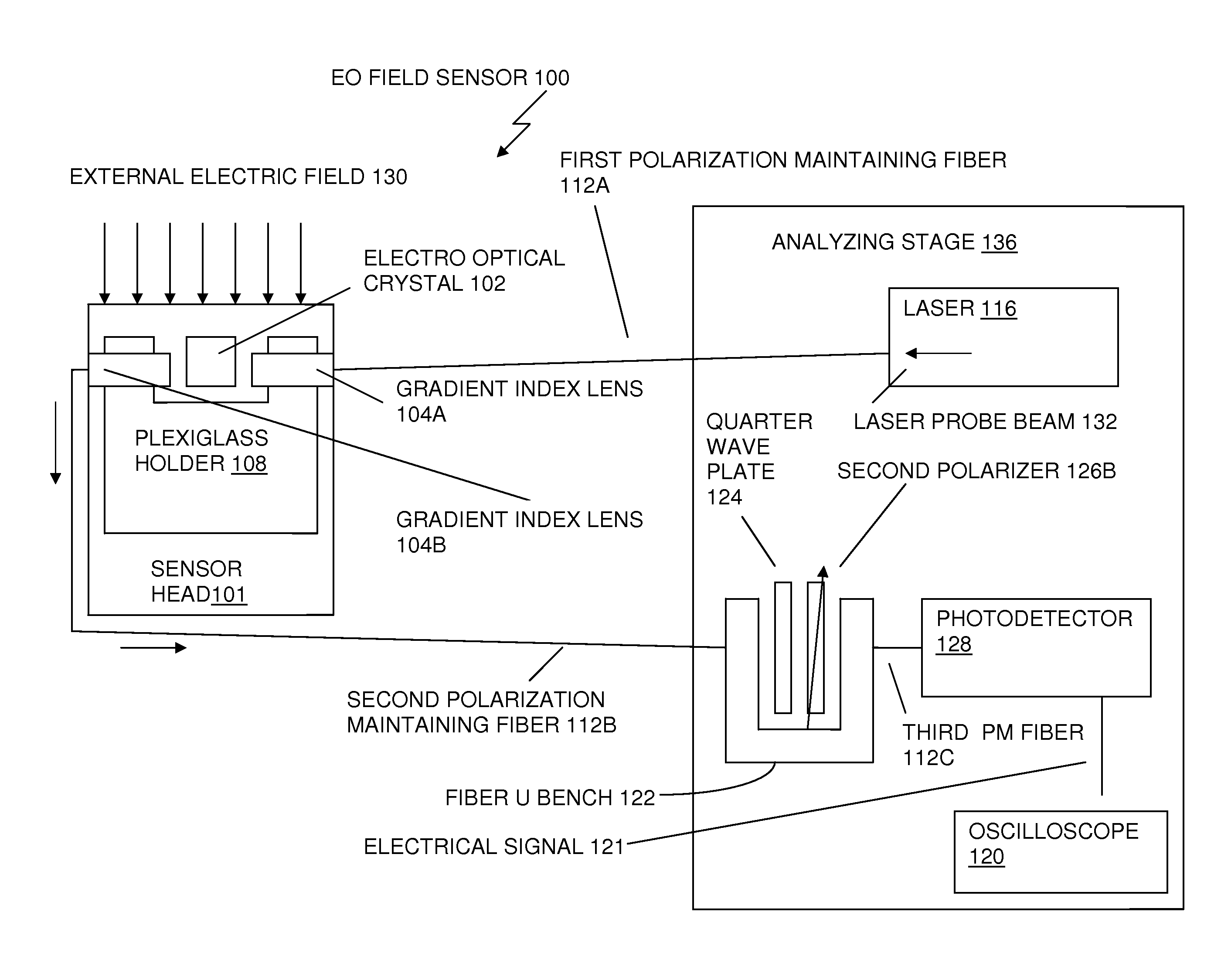
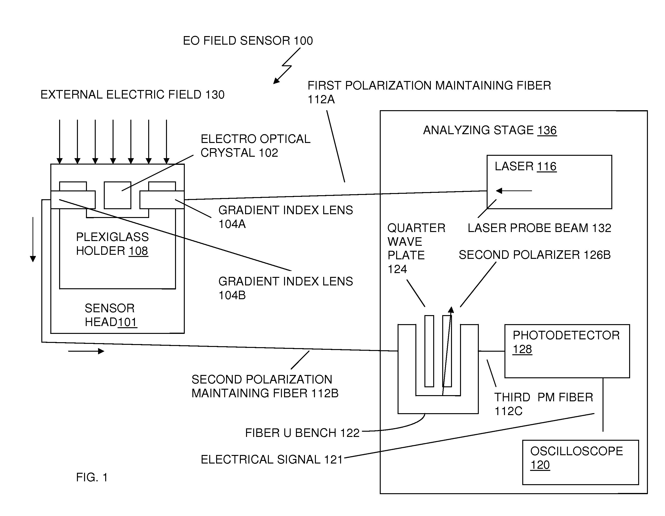
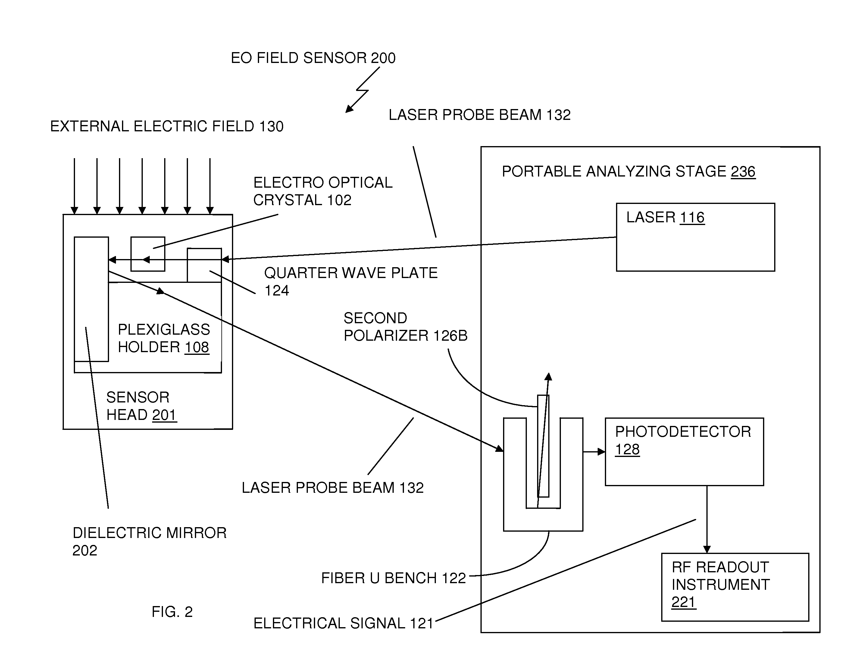
[0036]The instant application herein discloses a quasi-longitudinal-mode EO sensor employing an electro-optic crystal...


PUM


Abstract

An apparatus, for measuring an applied electrical field and for reducing perturbation to the electrical field being measured, includes a laser integrated into an electro optic crystal sensor head prior to the output fiber. A probe beam is passed along the crystal direction of low birefringence of nearly circular optical indicatrix, rather than one of high EO modulation. The EO crystal is placed between two crossed polarizers and oriented such that a small tilt angle is subtended between its optic axis and the path of the probe beam. Improved optical coupling is achieved by using a large core multimode fiber at the output, to reduce optical insertion losses. A collimating lens emits the intensity modulated laser beam back to a photodetector, where the intensity modulated laser beam is converted to an electrical signal representing both field strength and phase of the electrical field applied to the sensor head.

Description

RELATED APPLICATIONS[0001]Pursuant to 35 USC §120, the present application is related to and a continuation of and claims the benefit of priority to U.S. Non-Provisional patent application Ser. No. 12 / 205,766, filed on Sep. 5, 2008, now published application U.S. Patent Application Publication No. 2009-0066952, herein incorporated by reference in its entirety. Also, pursuant to 35 USC §119, the present application is related to and claims the benefit of priority to U.S. Provisional Patent Application 61 / 222,463 filed Jul. 1, 2009, which is herein incorporated by reference in its entirety.FIELD OF THE INVENTION[0002]The present invention is generally related to high power microwave test and evaluation. In particular the present invention is directed to an optical electromagnetic field sensor.[0003]A fundamental modification in the design of the optical fiber (EO) sensor is the subject of the exemplary embodiments described herein. The details of this new sensor structure are explaine...

Claims


Application Information

Patent Timeline
Patent Type & Authority Applications(United States)
IPC IPC(8): G01R13/38
CPCG01R31/308G01R29/0885
Inventor WU, DONG HOGARZARELLA, ANTHONY
Owner US GOVT REPRESENTED BY SEC OF NAVY CHIEF OF NAVAL RES
Why Eureka
Try Eureka