Liquid crystal cell substrate, liquid crystal cell, liquid crystal panel, and liquid crystal display

a liquid crystal cell and substrate technology, applied in the direction of liquid surface applicators, instruments, coatings, etc., can solve the problems of difficult control of optical characteristics such as the compounding ratio of optically active groups in the optical compensation layer formed of materials having optically active groups, and achieve the effect of reducing the thickness and weight of the liquid crystal cell substrate, reducing the weight and cost and reducing the thickness and weight of the liquid crystal cell

Active Publication Date: 2010-10-28
NITTO DENKO CORP
View PDF16 Cites 6 Cited by
  • Summary
  • Abstract
  • Description
  • Claims
  • Application Information

AI Technical Summary

Benefits of technology

[0009]The liquid crystal cell substrate of the present invention is obtained by laminating an optical compensation layer on a resin substrate, whereby reducing a weight and a cost of the liquid crystal cell substrate can be achieved as compared with those of the conventional liquid crystal cell substrate using a glass substrate. Further, the optical compensation layer has a refractive index distribution satisfying nx≧ny>nz and is formed by applying a material for formin...

Problems solved by technology

However, controlling optical characteristics such as controlling a compounding ratio of optically active gr...

Method used


Image

  • Liquid crystal cell substrate, liquid crystal cell, liquid crystal panel, and liquid crystal display
  • Liquid crystal cell substrate, liquid crystal cell, liquid crystal panel, and liquid crystal display
  • Liquid crystal cell substrate, liquid crystal cell, liquid crystal panel, and liquid crystal display

Examples


reference example 1

Production of Resin Substrate

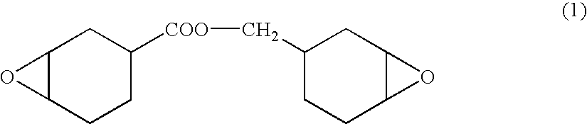
[0153]A mixture composed of 100 parts by weight of an alicyclic epoxy resin represented by the following formula (1), 125 parts by weight of methyl hexahydrophthalic acid anhydride, and 1 part by weight of tri-n-butyl octyl phosphonium bromide was poured into a mold and was subjected to a curing treatment for 2 hours at 120° C. Thus, a 0.4 mm thick resin substrate was obtained. A light transmittance of the resin substrate was 92%, and a glass transition temperature of the same was 210° C.

reference example 2

Preparation of Polyimide Solution

[0154]A 15% by mass polyimide solution was prepared by solving polyimide having a weight-average molecular weight (Mw) of 70,000 that is represented by the following formula (2) and is synthesized from 2,2-bis(3,4-dicarboxyphenyl) hexafluoropropane dianhydride (6FDA) and 2,2′-bis(trifluoromethyl)-4,4′-diamino biphenyl (TFMB) in cyclohexanone. It is to be noted that the preparation and the like of polyimide were conducted with reference to the method described in a document (F. Li et al. Polymer 40 (1999) 4571-4583).

example 1

Production of Liquid Crystal Cell Substrate

[0155]The polyimide solution of Reference Example 2 was applied on one side of the resin substrate of Reference Example 1 such that a thickness of a layer obtained by the application becomes 30 μm, and thereafter, the resin substrate was dried for 10 minutes at 120° C. Thus, a liquid crystal cell substrate having an optical compensation layer was obtained. The polyimide layer after drying had a thickness of 3 μm, satisfied Re(590)=0 nm and Rth(590)=250 nm, and exhibited negative uniaxiality satisfying nx=ny>nz. Further, the wavelength dispersion of this optical compensation layer exhibited a positive dispersion characteristic.


PUM


Abstract

The present invention provides a liquid crystal cell substrate, a liquid crystal panel, and a liquid crystal display whose thicknesses and weights can be reduced and optical characteristics at the time of producing them are easily controlled. The liquid crystal cell substrate 10 of the present invention is a liquid crystal cell substrate including a resin substrate 11 and an optical compensation layer 12, and the optical compensation layer 12 is laminated on the resin substrate 11. The optical compensation layer 12 has a refractive index distribution satisfying nx≧ny>nz, and the optical compensation layer 12 is formed by applying a material for forming an optical compensation layer to the resin substrate 11 or a base substrate that is different from the resin substrate 11.

Description

TECHNICAL FIELD[0001]The present invention relates to a liquid crystal cell substrate, a liquid crystal cell, a liquid crystal panel, and a liquid crystal display.BACKGROUND OF THE INVENTION[0002]Conventionally, with the aim of reducing a thickness, a weight, and a cost of a liquid crystal display, various analyses to substitute a glass substrate used for a liquid crystal panel with a resin substrate have been carried out. The liquid crystal display is basically configured so that glass substrates each on a flat plate provided with a transparent electrode are arranged to face each other through spacers so as to have a constant distance gap, a liquid-crystalline material is poured between the glass substrates and then sealed, thereby obtaining a liquid crystal cell, and further, polarizing plates are provided on exterior laterals of a pair of glass substrates. Since a resin substrate is inferior in smoothness and heat resistance to a glass substrate, the technology in which each laye...

Claims


Application Information

Patent Timeline
IPC IPC(8): G02F1/1335B05D5/06
CPCG02B5/3083G02F2202/02G02F2001/133565G02F1/133634G02F1/133565G02F1/13363
Inventor MURAKAMI, NAOYOSHIMI, HIROYUKI
Owner NITTO DENKO CORP
Why Eureka
Try Eureka