Method and jig assembly for manufacturing outer blade cutting wheel

a technology of cutting wheel and manufacturing method, which is applied in metal sawing tool making, grinding devices, liquid/solution decomposition chemical coatings, etc., can solve the problems of lowering the manufacturing yield, increasing the manufacturing cost, and the cost of the manufactured wheel over the prior art cutting wheel, and achieves low cost and high yield.

Active Publication Date: 2010-11-04
SHIN ETSU CHEM IND CO LTD
View PDF10 Cites 34 Cited by
  • Summary
  • Abstract
  • Description
  • Claims
  • Application Information

AI Technical Summary

Benefits of technology

[0047]Using the manufacturing method and jig assembly, a high-performance outer blade cutting wheel can be manufactured in high yields and at a low cost.

Problems solved by technology

Both the technique of binding abrasive grains to a cemented carbide base with a metal bond and the technique of shaping a blade section (or abrasive layer) of abrasive grains bound by a metal bond invite an extension of manufacture time and a lowering of manufacture yield, and eventually an increase of manufacture cost, as compared with the prior art well-known techniques.
The thus manufactured wheel is costly over the prior art outer blade cutting wheels.
Although the outer blade cutting wheel comprising a cemented carbide base and a metal-bonded abrasive grain blade shows higher performance in machining as compared with the prior art outer blade cutting wheels having a resin-bonded abrasive grain blade, the blade can be of higher cost.

Method used


Image

  • Method and jig assembly for manufacturing outer blade cutting wheel
  • Method and jig assembly for manufacturing outer blade cutting wheel
  • Method and jig assembly for manufacturing outer blade cutting wheel

Examples


example 1

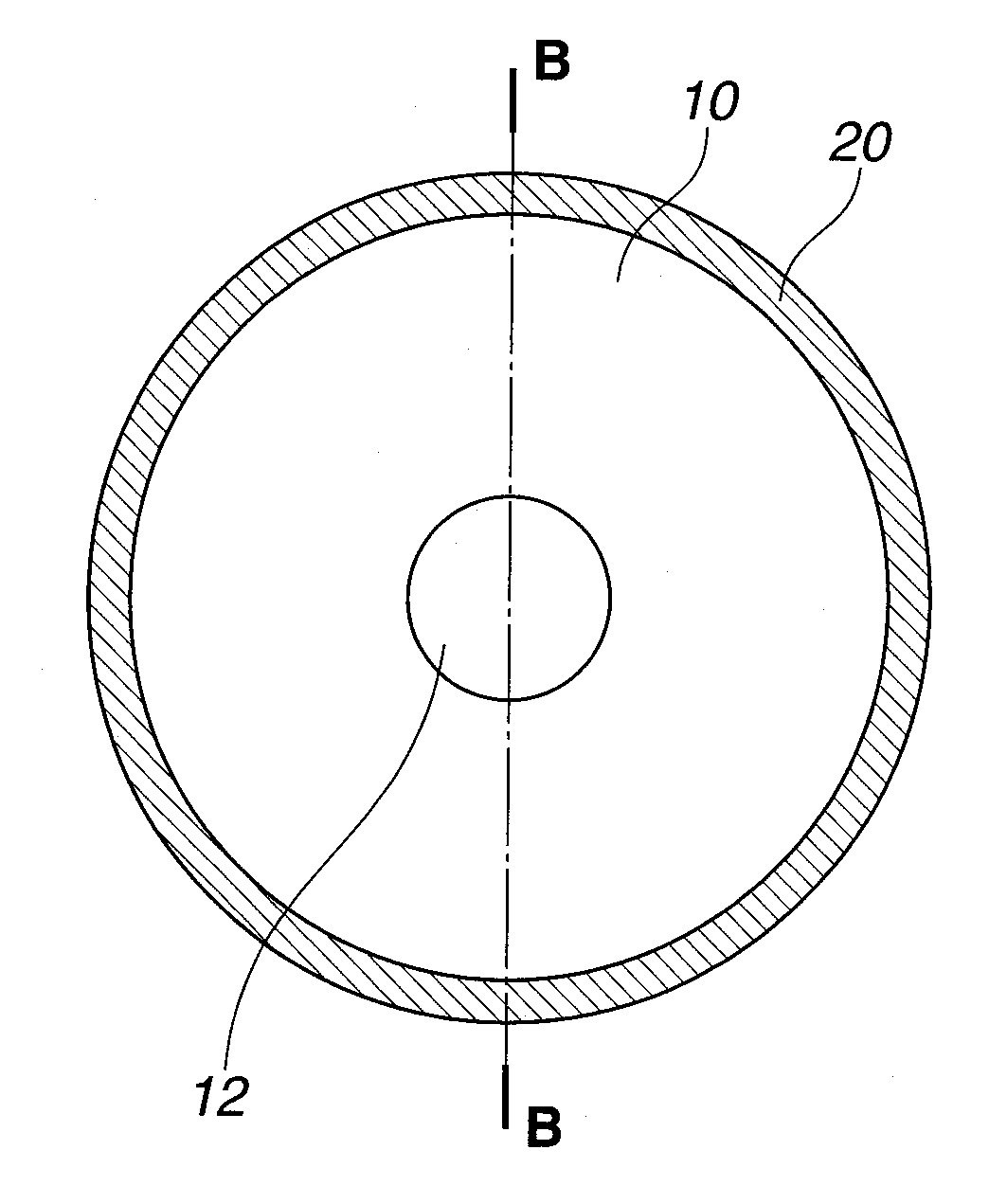
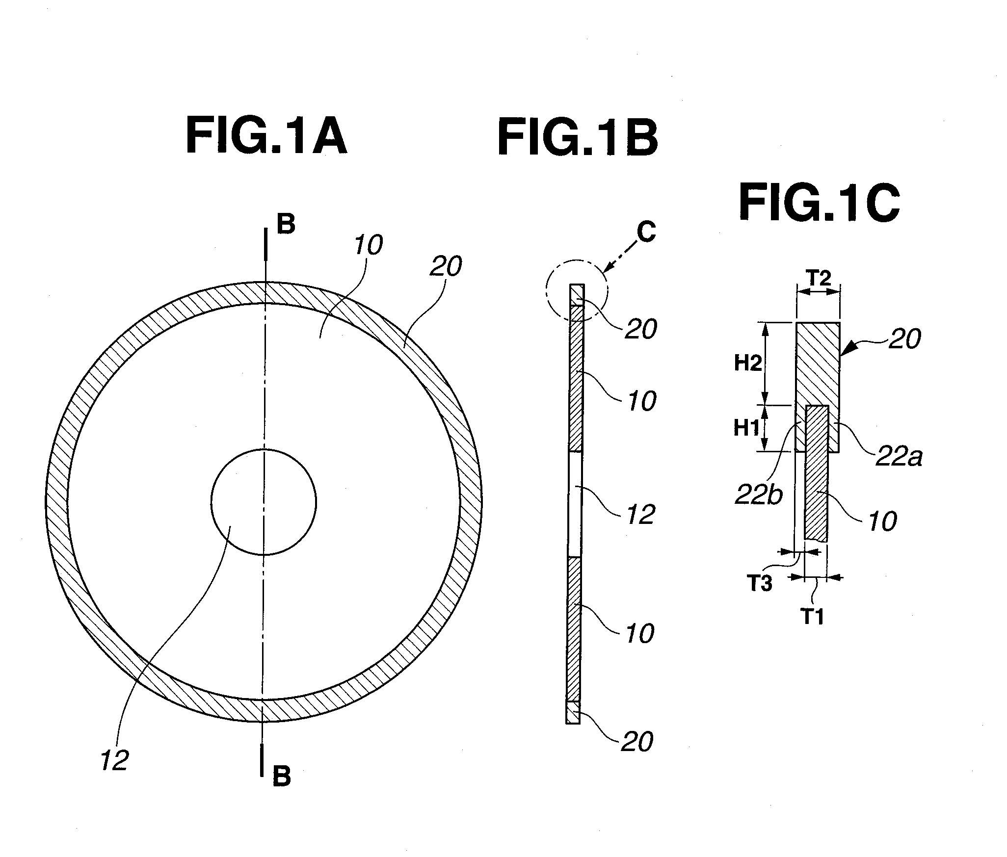
[0112]A cemented carbide consisting of 90 wt % WC and 10 wt % Co was machined into an annular thin disc having an outer diameter of 125 mm, an inner diameter of 40 mm, and a Young's modulus of 600 GPa and a saturation magnetization of 127 kA / m (0.16 T).

[0113]The base was masked with adhesive tape so that only a circumferential region of either surface extending 1.0 mm inward from the outer periphery was exposed. The base was immersed in a commercially available aqueous alkaline solution at 40° C. for 10 minutes for degreasing, washed with water, and immersed in an aqueous solution of 30-80 g / L of sodium pyrophosphate at 50° C. where electrolysis was effected at a current density of 2-8 A / dm2.

[0114]The cemented carbide base was ultrasonic washed in deionized water and immersed in a sulfamate Watts nickel electroplating bath at 50° C. where electricity was conducted at a current density of 5-20 A / dm2 for electroplating an underlayer. The masking tape was peeled off, and the base was w...

example 2

[0122]A cemented carbide consisting of 90 wt % WC and 10 wt % Co was machined into an annular thin disc having an outer diameter of 125 mm, an inner diameter of 40 mm, and a thickness of 0.3 mm, which served as a base. It had a Young's modulus of 600 GPa and a saturation magnetization of 127 kA / m (0.16 T).

[0123]The base was masked with adhesive tape so that only a circumferential region of either surface extending 1.5 mm inward from the outer periphery was exposed. The base was immersed in a commercially available aqueous alkaline solution at 40° C. for 10 minutes for degreasing, washed with water, and immersed in an aqueous solution of 30-80 g / L of sodium pyrophosphate at 50° C. where electrolysis was effected at a current density of 2-8 A / dm2.

[0124]The cemented carbide base was ultrasonic washed in deionized water and immersed in a sulfamate Watts nickel electroplating bath at 50° C. where electricity was conducted at a current density of 5-20 A / dm2 for electroplating an underlaye...

example 3

[0129]A cemented carbide consisting of 90 wt % WC and 10 wt % Co was machined into an annular thin disc having an outer diameter of 125 mm, an inner diameter of 40 mm, and a thickness of 0.3 mm, which served as a base. It had a Young's modulus of 600 GPa and a saturation magnetization of 127 kA / m (0.16 T).

[0130]The base was masked with adhesive tape so that only a circumferential region of either surface extending 1.0 mm inward from the outer periphery was exposed. The base was immersed in a commercially available aqueous alkaline solution at 40° C. for 10 minutes for degreasing, washed with water, and immersed in an aqueous solution of 30-80 g / L of sodium pyrophosphate at 50° C. where electrolysis was effected at a current density of 2-8 A / dm2.

[0131]The cemented carbide base was ultrasonic washed in deionized water and immersed in a sulfamate Watts nickel electroplating bath at 50° C. where electricity was conducted at a current density of 5-20 A / dm2 for electroplating an underlaye...


PUM

PropertyMeasurementUnit
remanenceaaaaaaaaaa
saturation magnetizationaaaaaaaaaa
Young's modulusaaaaaaaaaa

Abstract

An outer blade cutting wheel comprising an annular thin disc base of cemented carbide and a blade section is manufactured by disposing permanent magnet pieces on the side surfaces and inward of the outer periphery of the base to produce a magnetic field, providing magnetic coated diamond and / or CBN abrasive grains such that the magnetic field may act on the grains, causing the grains to be magnetically attracted to the base outer periphery, and electroplating or electroless plating whereby the abrasive grains are bound to the base outer periphery to form the blade section.

Description

CROSS-REFERENCE TO RELATED APPLICATION[0001]This non-provisional application claims priority under 35 U.S.C. §119(a) on Patent Application No. 2009-111762 filed in Japan on May 1, 2009, the entire contents of which are hereby incorporated by reference.TECHNICAL FIELD[0002]This invention relates to a method and jig assembly for manufacturing an outer blade cutting wheel for cutting rare earth sintered magnets.BACKGROUND ART[0003]Outer blade cutting wheels for cutting rare earth permanent magnets are disclosed in JP-A 9-174441, JP-A 10-175171, and JP-A 10-175172 as comprising a cemented carbide base having an outer periphery to which diamond abrasive grains are bonded with phenolic resins or the like. Since diamond grains are bonded to the cemented carbide base, the base has been improved mechanical strength over prior art alloy tool steel and high-speed steel bases, leading to a higher accuracy of machining. Also by reducing the thickness of the blade with using a cemented carbide ba...

Claims


Application Information

Patent Timeline
Patent Type & Authority Applications(United States)
IPC IPC(8): B24D5/12B25B11/00C25D5/34B24D3/00
CPCB23D61/028C25D7/001B24D3/06B24D5/12B24D18/0018C23C18/1608C23C18/1662C23C18/1673C23C18/1851C23C18/32C25D5/10C25D15/02C25D5/024C23C18/1896C23C18/1882B23D65/00C25D15/00B24D3/10B24D18/00B25B11/002C25D17/06
Inventor KASASHIMA, MASAKIDOI, YUHITOMAEGAWA, HARUKAZUMINOWA, TAKEHISA
Owner SHIN ETSU CHEM IND CO LTD
Why Eureka
Try Eureka