Apparatus and method for welding

a welding apparatus and welding method technology, applied in the field of welding, can solve the problems of insufficient devices, difficult to use devices, and relatively difficult to use devices, and achieve the effect of fine-tuning improving the fume extraction efficiency

Inactive Publication Date: 2010-11-04
COOPER PAUL +2
View PDF1 Cites 133 Cited by
  • Summary
  • Abstract
  • Description
  • Claims
  • Application Information

AI Technical Summary

Benefits of technology

[0036]Whereas, in the absence of the shroud gas port and the shrouding gas this flow (the ‘wall jet’) continues in a radially outward direction, surprisingly, the Applicants have found that by introducing a radially outward component of velocity to the shroud gas, when fume is extracted from the torch, the resulting wall jet flow is substantially contained and within the space around the weld pool shrouded by the shroud gas the direction of gas flow along the face of the work being welded is radially inwards. In other words, the shroud gas curtain tends to form an envelope around the welding site, thus isolating the fume generation region from the surroundings and allowing the fume gas to be extracted from within the envelope. The exiling shroud gas may be considered as a “radial gas jet” forming an “aer...

Problems solved by technology

However, this device is difficult to use because the size of the hood restricts the welding operator's line of sight to the welding site.
This device is also relatively difficult to use because the welding operator must constantly re-position the port above the arc to efficiently capture the fume as the torch is moved over the workpiece.
These devices have been found to be inadequate because in order to remove any fume, excessive suction is required.
Strong suction tends to draw away the essential shielding gas envelope from around the weld, thus adversely affecting weld quality, entraining air and potentially increasing fume generation.
This flow carries the bulk of the fume with it, with the result that the breathing zone of the operator is still likely to contain unacceptably high concentrations of the fume.
Whilst this configuration assists in confining the bulk of the ...

Method used


Image

  • Apparatus and method for welding
  • Apparatus and method for welding
  • Apparatus and method for welding

Examples


examples

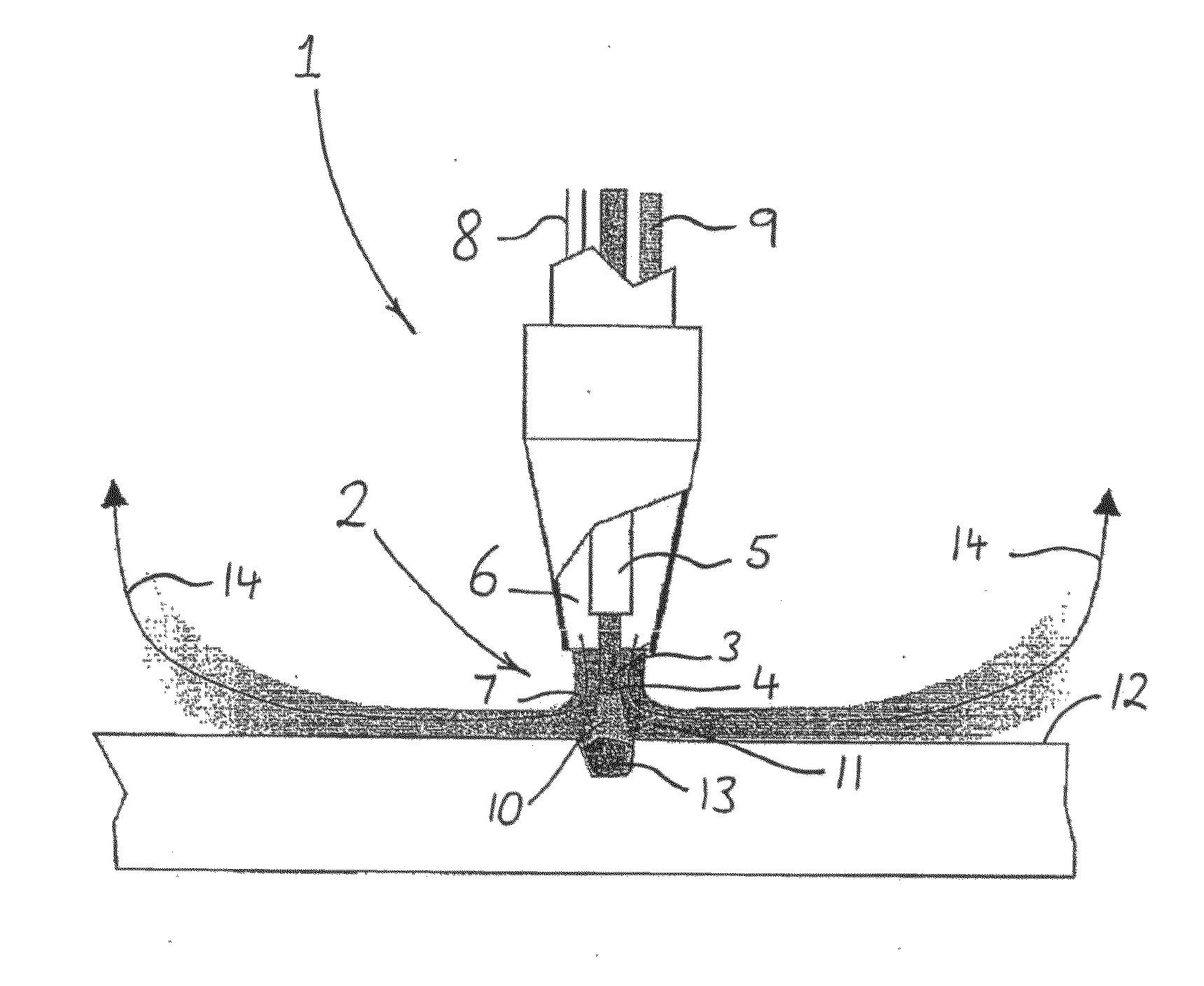
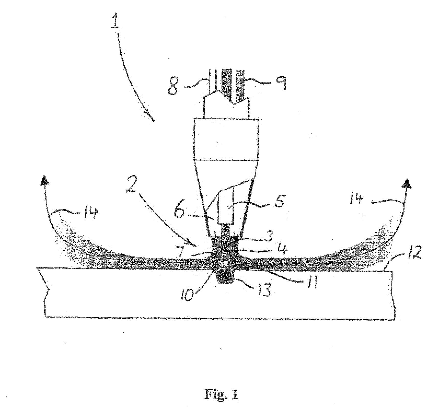
[0069]In one example, a commercial GMAW torch adapted according to the present invention was configured with a 1.2 mm Autocraft LW1 welding wire / electrode and Argoshield® Universal gas. Test conditions were chosen to provide “high fume”, i.e. 250 Amps at 32 Volts. The welding torch was configured to provide “stand oft” distances of: workpiece to torch nozzle=22 mm; workpiece to shroud gas curtain (radial jet)=22 mm and 32 mm (22 mm maximum efficiency and 32 mm maximum weld pool visibility); and radial distance welding wire / electrode to shroud gas curtain (radial jet) outlet=40 mm. Better than 85% fume removal was achieved with 22 mm radial jet stand off.

[0070]In other examples, welding tests were conducted wherein the extraction flow rate was held constant at 101 / min and the shroud gas flow rate was varied for 3 different shielding gas flow rates, viz 25, 30 and 35 l / min. As can be seen in FIG. 6, the extraction efficiency was plotted as a function of the ratio of shroud gas flow ra...


PUM

PropertyMeasurementUnit
Flow rateaaaaaaaaaa
Areaaaaaaaaaaa
Velocityaaaaaaaaaa

Abstract

The present invention relates to arc welding torch and a method of extracting fume gas from a welding site. The torch comprises a metal electrode and at least one shield gas port adapted to direct a shield gas curtain around the metal electrode and a welding site. At least one shroud gas port is spaced radially outward from the shield gas port and adapted to impart to an exiting shroud gas a radially outward component of velocity. Fume gas is preferably extracted from a position radially intermediate the shield gas curtain and the shroud gas curtain.

Description

FIELD OF THE INVENTION[0001]The present invention relates to welding, and in particular to a welding method and apparatus providing improved fume gas extraction efficiency.BACKGROUND OF THE INVENTION[0002]Any discussion of the prior art throughout the specification should in no way be considered as an admission that such prior art is widely known or forms part of the common general knowledge in the field.[0003]Welding is key enabling technology in many sectors of industry. For example, Gas Metal Arc Welding (GMAW), sometimes referred to as Metal Inert Gas (MIG) or Metal Active Gas (MAG) welding accounts for some 45% of all weld metal deposited in Australia (Kuebler. R., Selection of Welding Consumables and Processes to Optimise Weld Quality and Productivity, Proceedings of the 53rd WTIA Annual Conference, Darwin, 11-13 October 2005).[0004]In GMAW, the intense heat needed to melt the metal is provided by an electric arc struck between a consumable electrode and the workpiece. The wel...

Claims


Application Information

Patent Timeline
IPC IPC(8): B23K9/16
CPCB08B15/04B23K9/173B23K9/296B23K35/38B23K35/22B23K35/368B23K9/325B23K9/26
Inventor COOPER, PAULGODBOLB, AJITNORRISH, JOHN
Owner COOPER PAUL
Why Eureka
Try Eureka