[0022]A unique wall panel is constructed from
expanded polystyrene beads in an
expanded polystyrene mold with structural members embedded in it during the molding process. The structural members are in the form of two by four studs placed at sixteen inch centers. Adjacent panels have
interlocking grooves and ridges which fit together. The
advantage of the present invention is that a total insulated wall is created with no cracks or spaces in the insulation. These lightweight panels can be carried to the building site, where base and top plates are applied and the panels interlocked to form a perfectly insulated wall. CL U.S. Pat. No. 5,265,389
[0023]A composite building panel includes a core of a foamed polymeric insulating material, such as
expanded polystyrene, having a plurality of uniformly spaced open box tubes retained in vertical grooves formed in the rear surface of the core by a two-part
epoxy adhesive, the tubes being mechanically connected at their ends to one leg of continuous horizontal channels having their other leg adhesively secured to the core at horizontal slots. The front surface of the core is continuous without seams and may be coated with a variety of
exterior insulation finishing system coatings. CL U.S. Pat. No. 5,269,109Inventor: V. Rao GularIssued: Dec. 14, 1993
[0024]An insulated
load bearing wall (10, 10′) comprising panels of extruded
polymer foam (20, 22, 50, 52, 54, 56) into which tubular,
load carrying frame members (12, 14, 48) have been incorporated. A tongue is formed at one
vertical edge of each panel (10, 10′) and a groove is formed at the opposite
vertical edge. The tubular frame members (12, 14, 48) are bonded to the extruded
polymer foam. CL U.S. Pat. No. 5,765,330Inventor: Michel V. RichardIssued: Jun. 16, 1998
[0025]A pre-insulated prefab wall panel comprising of a rectangular wall frame having top and bottom rail members and a plurality of spaced apart stud members aligned between the top and bottom rail members. A
polystyrene boardstock is affixed to a first side of the rectangular wall frame, thereby defining with the top and bottom rail members and the plurality of stud members a plurality of rectangular cavities, wherein each cavity has a depth of the thickness of a stud member. The prefab wall panel further has a layer of foamed-in-place
polyurethane covering a portion of each cavity adjoining the boardstock, and bonding the structural wall frame to the
polystyrene boardstock. The layer of
polyurethane foam has a thickness which is substantially less than the depth of each cavity, whereby each cavity has available space for accommodating sub-trade installations. CL U.S. Pat. No. 5,953,883Inventor: Leo V. OjalaIssued: Sep. 21, 1999
[0026]An insulated wall panel comprising a bottom, a plurality of inner members, a plurality of outer members, spacers between the inner members and the outer members, an
insulation layer, an exterior sheathing, a
vapor barrier, a top member and a planar interior wall. The insulated wall panel has a dead
air space located just inside of a cavity filled with insulation. The wall panel is adapted to be secured to the frame of a timber frame home without fasteners passing through the entire depth of the panel. Fasteners secure the inner members of the panel only to the frame without destroying the integrity of the insulated wall panel. CL U.S. Pat. No. 6,158,190Inventor: Stephen SengIssued: Dec. 12, 2000
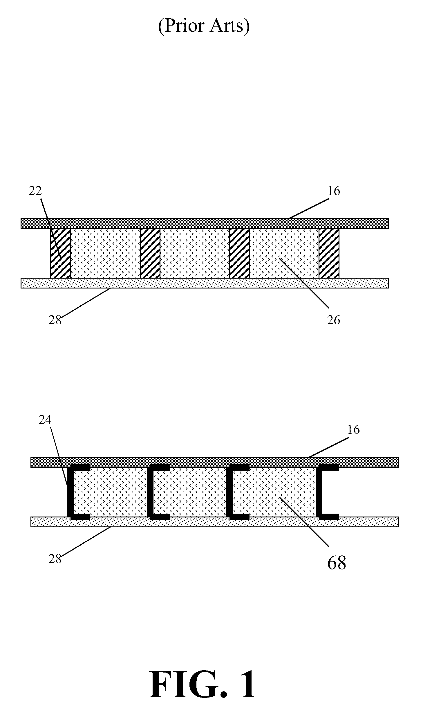
[0027]This composite building stud combines two
metal shapes, inner and outer, with an insulating material to form a composite structural member having an insulating valve (R-value) greater than a similar
metal member normally used as a stud in a residential structure. The composite also has a strength comparable to that of a similar steel member normally used as a stud in a residential structure. One shape encompasses the other shape. The composite structural member eliminates any direct
metal connections and thus eliminates any thermal shorts that reduce the overall insulating value (R-value) of the composite member. The shapes, inner and outer, with an insulating material form a composite structural member that has an
interlocking shape which holds the insulating material in compression and mechanically couples the inner and outer members. CL U.S. Pat. No. 6,857,237Inventor: Raymond F. Dalphond, et al.Issued: Feb. 22, 2005

