Laser beam machining

a laser beam and laser beam technology, applied in the direction of photomechanical equipment, instruments, manufacturing tools, etc., can solve the problems of insufficient autofocus quality of such systems, difficult or even impossible reference of the absolute position of the focus, and insufficient accuracy of the autofocus system, etc., and achieve the effect of high precision

Active Publication Date: 2010-11-25
NANOSCRIBE HLDG GMBH
View PDF36 Cites 45 Cited by
  • Summary
  • Abstract
  • Description
  • Claims
  • Application Information

AI Technical Summary

Benefits of technology

[0013]The invention is therefore based on the object of providing a method and an apparatus with which laser...

Problems solved by technology

The problem arises however that the referencing of the absolute position of the focus is often very difficult or even impossible, and can especially change during the machining process.
In the case of conventional sizes of workpieces which are machined with laser scanning lithography, the autofocus quality of such systems would be insufficient.
A triangulation method is therefore usually performed iteratively, which is relatively time-consuming.
The fact that workpieces machined by means of two-photon processes are usually transparent represents a problem here because there are no structures in the workpiec...

Method used


Image

  • Laser beam machining
  • Laser beam machining
  • Laser beam machining

Examples


Embodiment Construction

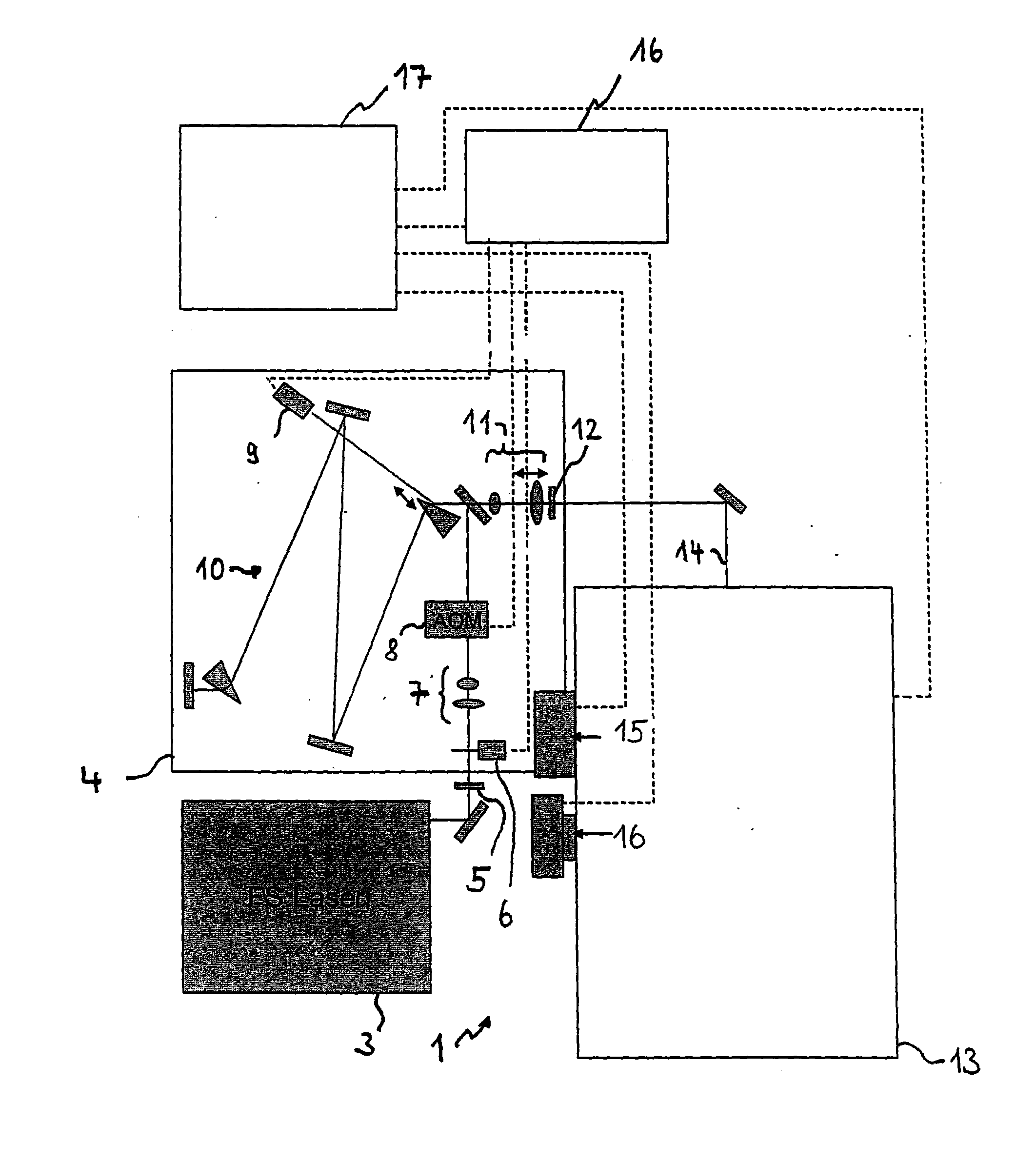
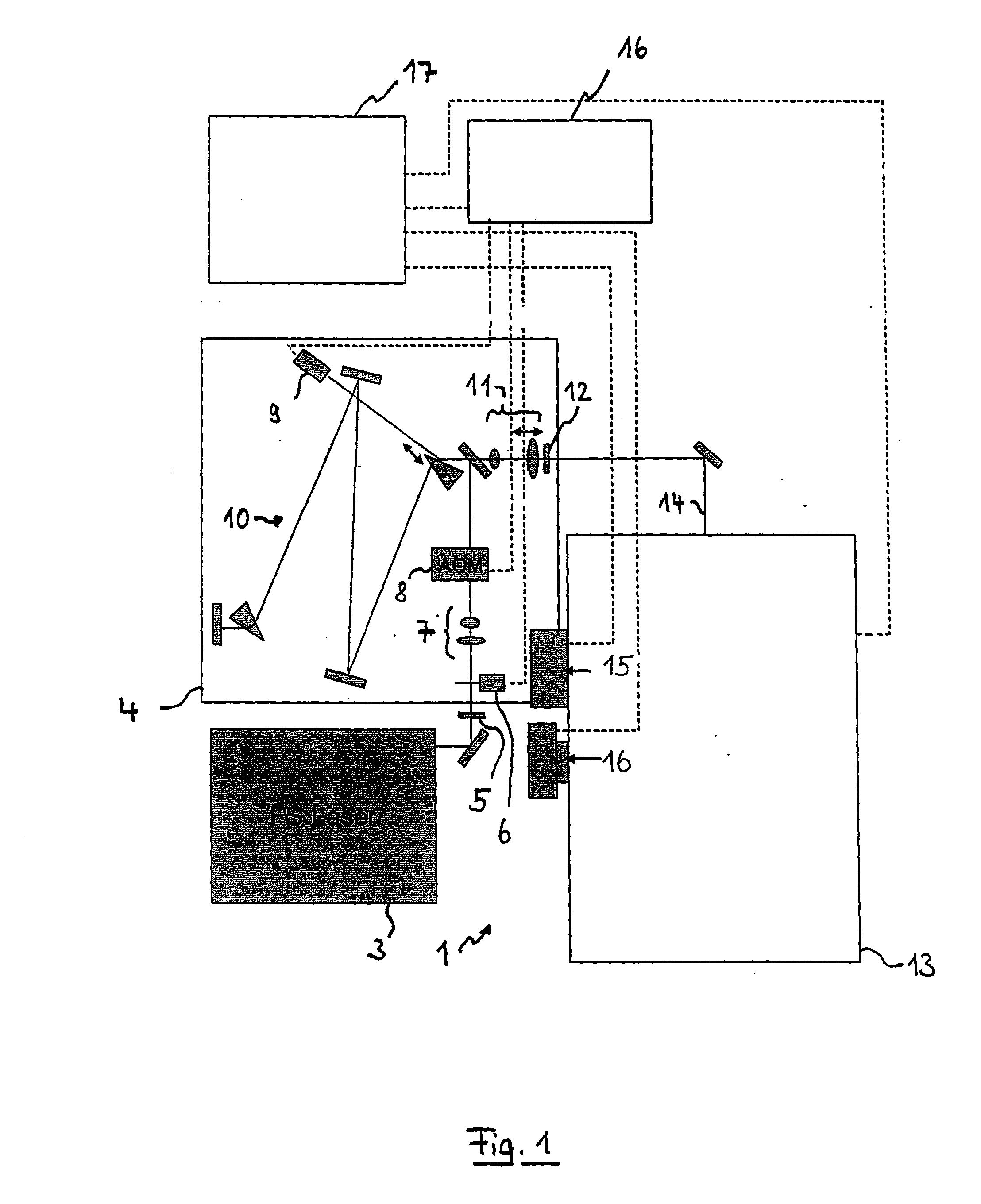
[0058]FIG. 1 shows a laser scanning microscope 1 with which a multi-dimensional structure is produced by means of direct laser writing (i.e. per laser scanning lithography) in a workpiece which can be a polymer layer on a substrate for example. A two-photon process is used.

[0059]The illustration in FIG. 1 is greatly simplified. The microscope 1 uses a pulsed laser 3, e.g. an fs-laser, as a radiation source for the laser writing. The radiation of the laser 3, e.g. with a mean wavelength of 780 nm for example, is shaped in a pulse conditioner 4 into fs-pulses. For this purpose, the radiation is guided at first via a ½ wavelength plate 5, a mechanical shutter 6, a telescope 7, and an acousto-optical modulator (AOM) 8 and thus controlled in its intensity. The monitoring of the control (e.g. per closed-loop feedback) occurs via a monitor diode 9 which receives a share of the radiation.

[0060]After suitable setting of the group velocity dispersion (GVD) by means of a GVD module 10 in order...


PUM

PropertyMeasurementUnit
Angleaaaaaaaaaa
Structureaaaaaaaaaa
Distanceaaaaaaaaaa

Abstract

A method for laser beam machining of a workpiece in which a laser beam is focused by an objective, into or onto the workpiece having a boundary surface, to produce a machining effect by a two-photon process, and the position of the focal point with respect to the workpiece is shifted. To obtain a reference for the position of the focal point, an image of a luminating modulation object is projected through the objective onto the workpiece into the focal plane or so as to intersect it. Reflections of the image occurring at the boundary surface are imaged into an autofocus image plane, and are detected by a camera. The camera image plane either intersects the autofocus image plane when the image of the illuminating modulation object lies in the focal plane, or lies in the autofocus image plane when the image of the modulation object intersects the focal plane.

Description

PRIORITY CLAIM[0001]The present application is a National Phase entry of PCT Application No. PCT / EP2008 / 009840, filed Nov. 20, 2008, which claims priority from German Application Number 102007055530.1, filed Nov. 21, 2007, the disclosures of which are hereby incorporated by reference herein in their entirety.FIELD OF THE INVENTION[0002]The invention relates to an apparatus and a method for laser machining a workpiece by two-photon processes.BACKGROUND[0003]Laser beam machining of a workpiece by two-photon processes usually occurs by shifting a laser beam focus over or in the workpiece and is also known as laser writing or laser scanning lithography. Apparatuses and methods for this purpose are known from the state of the art and usually utilize the polymerization of a workpiece, e.g. of a photosensitive resist. A respective description can be found in J.-M. Lourtioz, Nature Materials 3, 427 (2004) and M. Deubel et al., Nature Materials 3, 444 (2004). A microscope for laser beam writ...

Claims


Application Information

Patent Timeline
IPC IPC(8): B23K26/06
CPCB23K26/046G02B7/32G03F7/70383G02B21/245G03F7/70375G02B21/244
Inventor KEMPE, MICHAELWESTPHAL, PETERGRAU, WOLFGANGVON FREYMANN, GEORG
Owner NANOSCRIBE HLDG GMBH
Why Eureka
Try Eureka