Sea surface cooling system utilizing otec

a technology of sea surface cooling and otec, which is applied in the direction of sea energy generation, mechanical equipment, machines/engines, etc., can solve the problems of low conversion efficiency, low energy conversion efficiency of power generation plants utilizing otec, and inability to achieve significant improvement in efficiency, etc., to achieve the effect of lowering energy conversion efficiency, abundance of energy resources, and low conversion efficiency

Inactive Publication Date: 2010-12-02
SAKURAI TOSHIHIKO
View PDF7 Cites 21 Cited by
  • Summary
  • Abstract
  • Description
  • Claims
  • Application Information

AI Technical Summary

Benefits of technology

[0019]Although the energy conversion efficiency of a power generation plant utilizing OTEC is low, the effect of such a plant on cooling the sea surface and the abundance of energy resources necessary for implementing the plant are obvious. The sea surface cooling has not been an original objective for OTEC, but rather an undesirable side effect for lowering energy conversion efficiency by decreasing temperature diffe...

Problems solved by technology

This low conversion efficiency is due to a principle of thermodynamics that makes any significant improvement in efficiency unlikely.
However, commercial power plants employing OTEC appear to be lagging behind clean energy power plants utilizing other types of natural energy resources.
Nevertheless, power generation systems utilizing clean energy resources have been developed with the primary objective of reducing CO2 rather than achieving highly efficient energy conversion.
This means that, while global warming continues to progress due primarily to CO2 as the main greenhouse gas, there is a frightening possibility that thermal runaway awaits in the future, whereby water vapor would replace CO2 as the predominant greenhouse gas.
In other words, reducing CO2 emissions is no longer the best way to prevent thermal runaway.
However this application will be somewhat more difficult than producing a...

Method used


Image

  • Sea surface cooling system utilizing otec
  • Sea surface cooling system utilizing otec
  • Sea surface cooling system utilizing otec

Examples


first embodiment

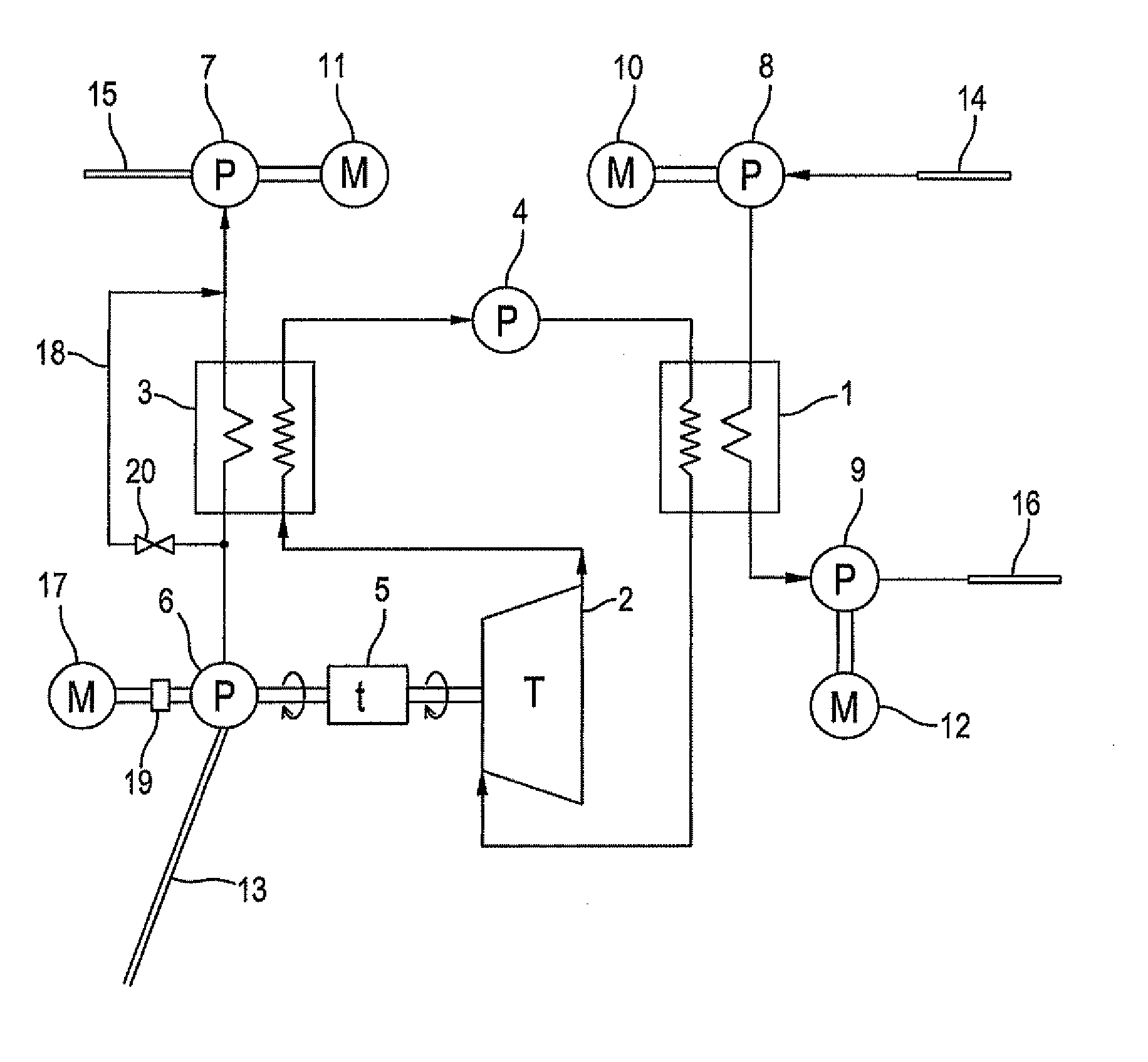
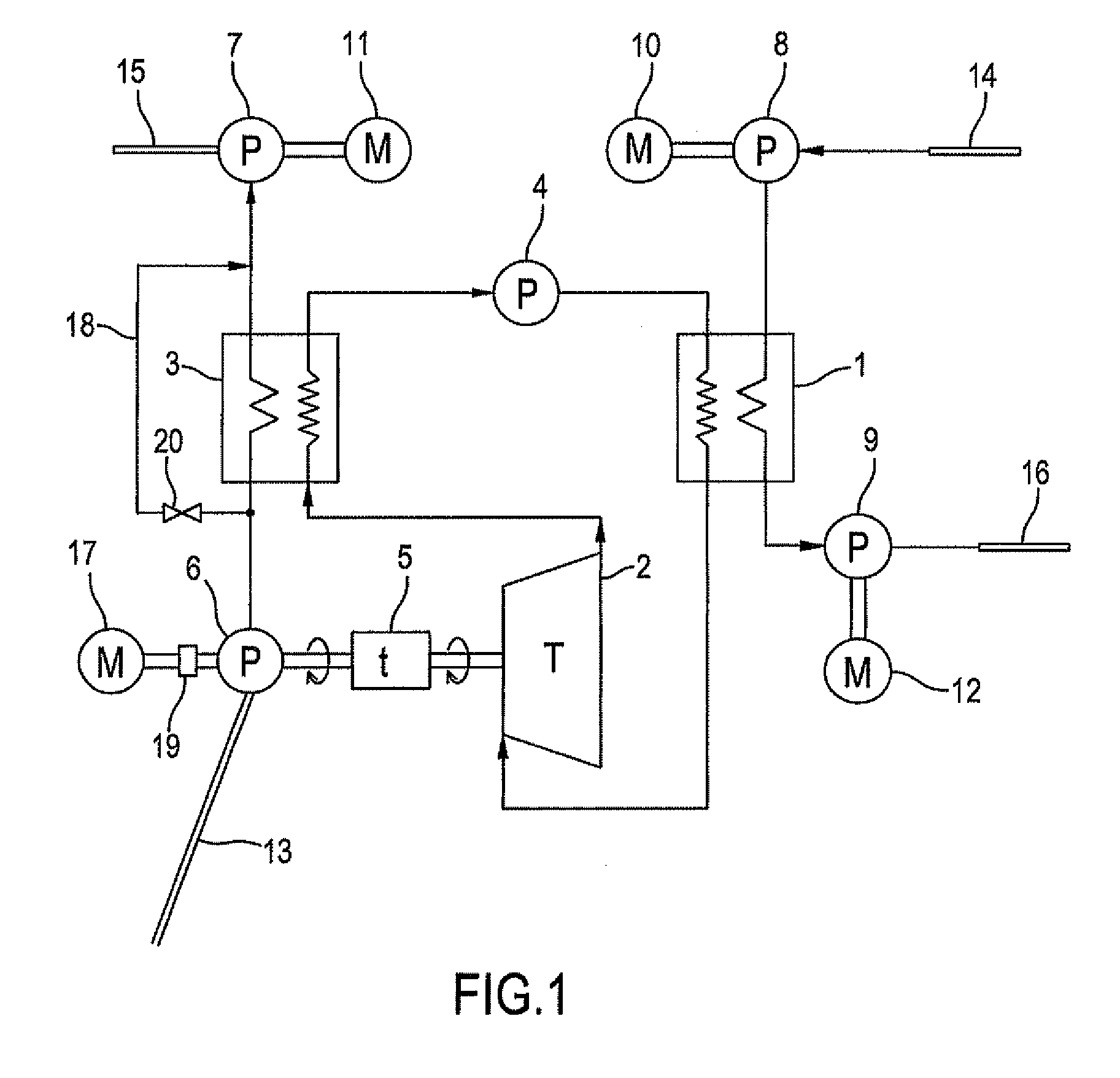
[0121]FIG. 1 is a functional block diagram showing a construction of the sea surface cooling system according to the first embodiment of the present invention. In the figure, reference number 1 denotes an evaporator, 2 a turbine, 3 a condenser, 4 a circulation pump, 5 a transmission for rotary power, 6 a deep seawater draw pump, 7 and 9 drain pumps, 8 a surface seawater draw pump, 10, 11, and 12 electric motors, 13 a deep seawater draw pipe, 14 a surface seawater draw pipe, 15 a deep seawater drainpipe, 16 a surface seawater drainpipe, 17 a starter motor, 18 a bypass pipe, 19 a coupling / decoupling unit, and 20 a stop valve.

[0122]Although many of the elements are shown in a singular form, they may actually consist of a plurality of the same elements of a smaller size that are connected in parallel or in cascade and work in synchronization with each other.

[0123]The sea surface cooling system shown in FIG. 1 is a modification of a typical closed-cycle OTEC power plant utilizing a worki...

second embodiment

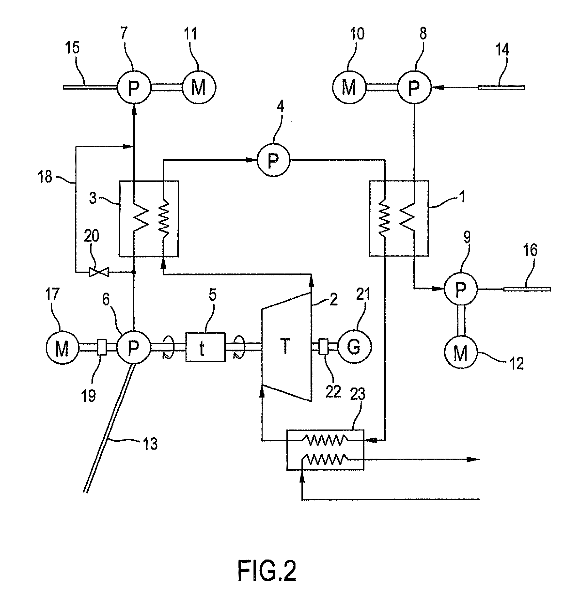
[0167]FIG. 2 is a block diagram showing a sea surface cooling system according to a second embodiment of the present invention. In FIG. 2, elements denoted by the same reference numbers used in FIG. 1 are the same elements as those denoted by the corresponding reference numbers and were already explained while referring to FIG. 1. Therefore, a duplicate explanation for these elements will be omitted. In the second embodiment, a generator 21 is newly installed and is coupled to the other end of turbine 2 through a coupling / decoupling unit 22.

[0168]A condensation-type solar power generating system employing a solar battery is constructed nearby. An example of this type of solar power generating system is disclosed in the preceding patent application US20100018567 by the present inventor. This system includes a two-dimensional reflector to condense solar energy on the solar cells located along its focal line, and means for discharging hot drainage, which was used to cool the solar cell...


PUM


Abstract

A sea surface cooling system utilizing OTEC of the present invention comprises means for drawing surface seawater, deep seawater pumping means for pumping deep seawater through a draw pipe, evaporator means for heating and vaporizing working fluid with a low boiling point by said drawn surface seawater, mechanical power producing means for producing mechanical power by expansion force of said vaporized working fluid, condensation means for cooling said vaporized working fluid after said expansion by said pumped deep seawater to cause condensation, and means for circulating said condensed working fluid to said evaporator means. The system is characterized by including mechanical power transmission means for directly transmitting from said mechanical power producing means to said pumping means a mechanical power of variable ratio, without once converting said mechanical power into electric power.

Description

BACKGROUND OF THE INVENTION[0001]1. Field of the Invention[0002]This invention relates in general to a sea surface cooling system, and particularly to a system that utilizes OTEC (Ocean Thermal Energy Conversion) to generate mechanical power for pumping cool deep seawater upward for cooling the hot sea surface.[0003]2. Description of Related Art[0004]Recently, various clean power generating systems have been developed to utilize a variety of natural energy resources other than conventional fossil fuels because fossil fuels emit carbon dioxide (CO2), a harmful greenhouse gas that promotes global warming. These clean energy resources include solar energy, wind energy, wave energy, tidal energy, and ocean thermal energy. The present inventor has previously filed a patent application titled Solar Power Generating System Employing a Solar Battery (US20100018567).[0005]In a power generation system utilizing OTEC, the temperature difference between hot surface seawater and cold deep seawat...

Claims


Application Information

Patent Timeline
IPC IPC(8): F03G7/04
CPCY02E10/34F03G7/04Y02E10/30
Inventor SAKURAI, TOSHIHIKO
Owner SAKURAI TOSHIHIKO
Why Eureka
Try Eureka