

Microbial fuel cell
a fuel cell and microorganism technology, applied in the direction of fuel cells, electrochemical generators, electrical equipment, etc., can solve the problems of low performance, complicated construction of mea, and strategy that does not solve the limitations of cation diffusion
- Summary
- Abstract
- Description
- Claims
- Application Information
AI Technical Summary
Benefits of technology
Problems solved by technology
Method used
Image

Examples
example 1
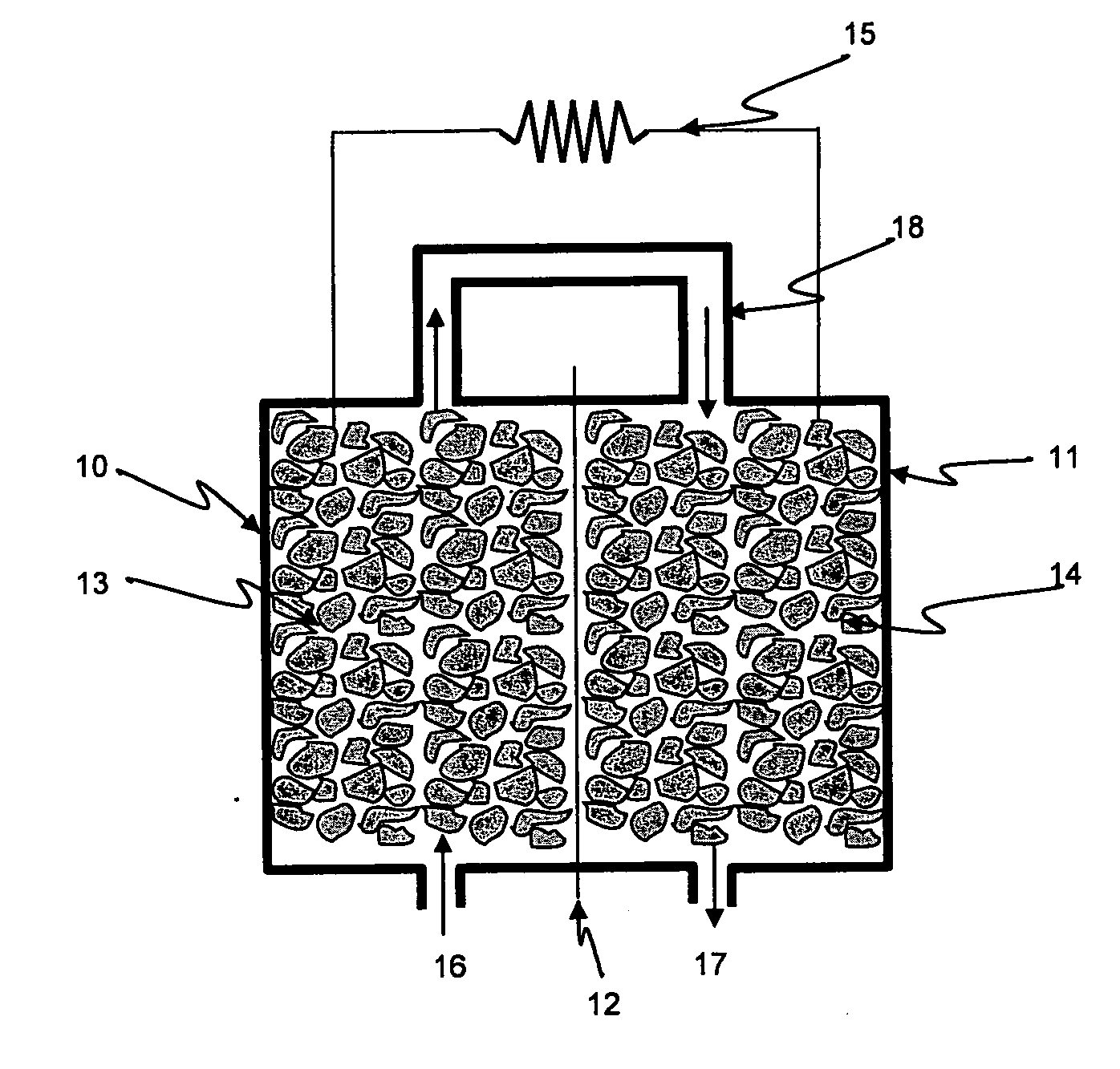
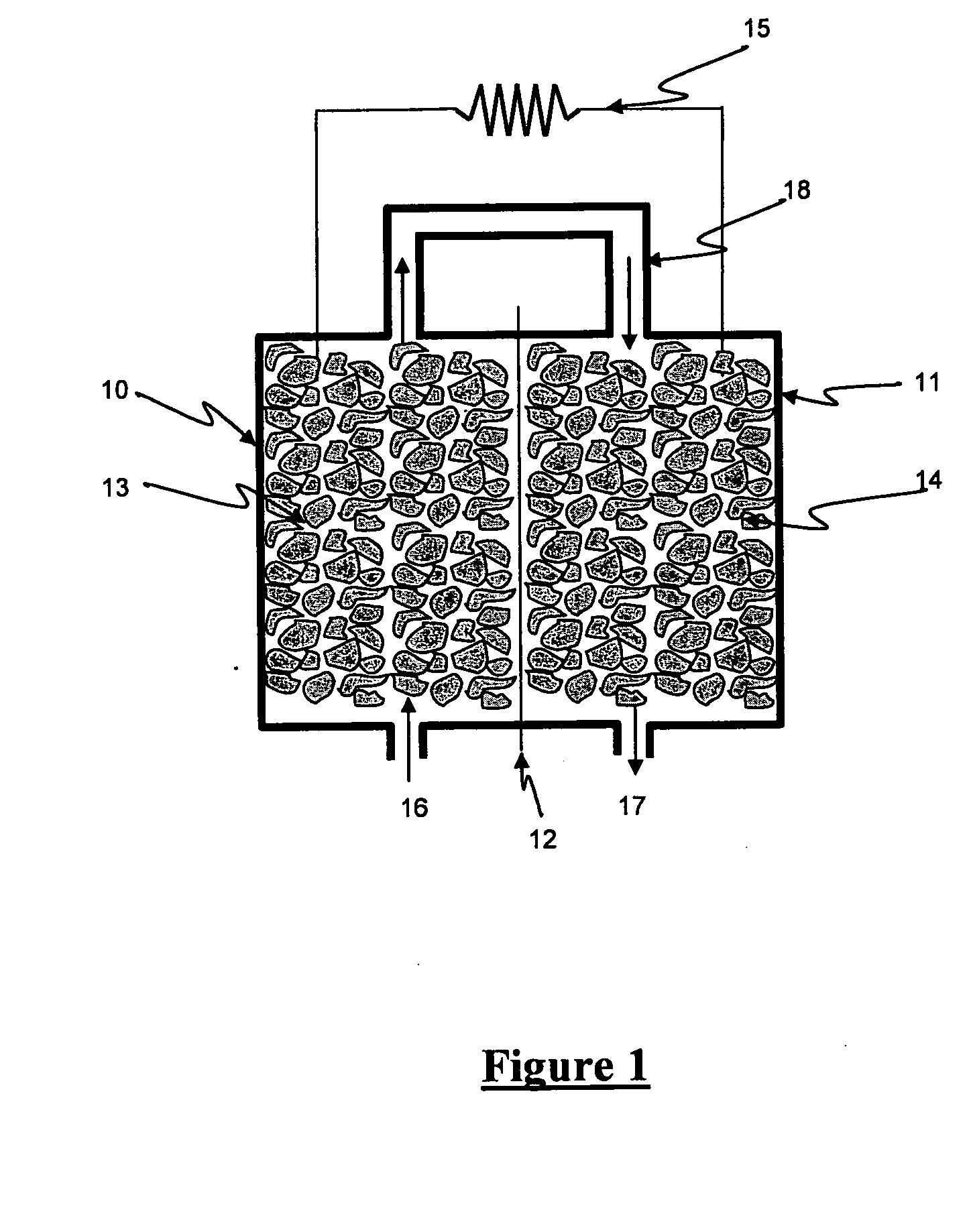
[0031]In this example a microbial fuel cell was used to test the ability of the loop concept to perform COD polishing and effluent pH control at different loading rates while not losing performance in terms of current production. The microbial fuel cell comprised of an anode containing granular graphite (El Carb 100, Graphite Sales Inc, USA) supporting the growth of an anodophilic biofilm and a cathode of the same graphite supporting a cathodophilic biofilm, with oxygen provided with an air sparger. The cation exchange membrane (Ultrex, CMI-7000, Membranes International, USA) separated the two compartments and the anode effluent was used as cathode influent as shown in the loop connection. The external circuit was closed on a resistor of 10 Ohm.
[0032]The feed to the microbial fuel cell contained a medium with composition 6 g / L NaH2PO4, 3 g / L KH2PO4, 0.1 g / L NH4Cl, 0.5 g / L NaCl, 0.1 g / L MgSO4.7H2O, 15 mg / L CaCl2.2H2O, 1.0 mL / L of a trace elements solution. The carbon source and elect...
example 2
[0034]A microbial fuel cell was used to test the possibility of obtaining simultaneous carbon and nitrogen removal. The microbial fuel cell was made of two rectangular Perspex frames (dimensions 14×12×2 cm) placed side by side and held together by two equal Perspex square plates with threaded rods and wing nuts. The cation exchange membrane (Ultrex CMI-7000, Membranes International, USA) was placed in between the two compartments. Wet seal was ensured by rubber sheets inserted between every frame. Granular graphite with diameter ranging from 2 to 6 mm (El Carb 100, Graphite Sales, Inc., USA) was used as conductive material in both compartments.
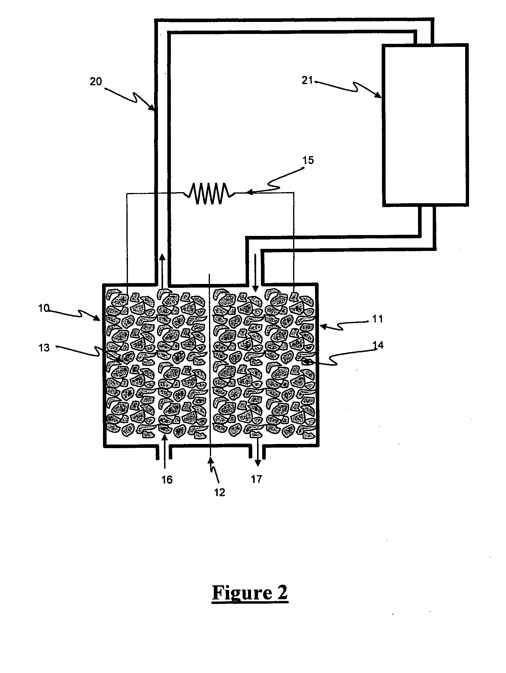
[0035]The loop concept is applied as the liquid stream passes through the anode and then goes into an external aerobic stage which interposes in between the two anodic and cathodic stages and is then diverted again in the cathodic side of the microbial fuel cell. The aerobic stage consists of a trickling bed reactor where the liquid is sprayed...
example 3
[0039]In this example microbial fuel cells were constructed following the embodiment in FIG. 6. Pre-fermented wastewater from a brewery was used as influent for the anode. The microbial fuel cells were three meters high, diameter 0.20 m. The membrane around the anode (carbon fiber brushes) was ULTREX. The cathode consisted of carbon fiber brushes, attached to a stainless steel mesh. Wastewater was brought on the recirculation loop, first entered the anode where oxidation of the pollutants was achieved. The effluent of the anode was brought to the cathode, where oxygen reduction took place. The effluent of the cathode was captured in a sump, from where it entered the recirculation loop again. Effluent was discharged from the sump. When applying an external resistor of 0.4 Ω, a cell voltage of 0.6 Volts could be generated, implying a current of 1.5 A. This corresponds to a removal of 430 g of organics (expressed as chemical oxygen demand) per cubic metre anode volume per day from the ...
PUM
 Abstract
Description
Claims
Application Information