Unlock instant, AI-driven research and patent intelligence for your innovation.

Cutting system for fouling removal from jet drive water intake

a technology of cutting system and water intake, which is applied in the direction of marine propulsion, hulls, vessel construction, etc., can solve the problems of substantial reduction of thrust capability, excessive grating, and substantial blockage of intake, so as to improve performance, eliminate the separation of blades, and enhance performance

Inactive Publication Date: 2010-12-02
DJC MARINE TECH
View PDF21 Cites 0 Cited by
  • Summary
  • Abstract
  • Description
  • Claims
  • Application Information

AI Technical Summary

Benefits of technology

"The present invention is a cutting system for removing fouling materials from the intake of a water-jet drive and impeller. The system includes a cutting blade and guide tines to restrict vertical movement of the blade as it passes along the surface of the intake grate. The cutting blade is moved by an actuator system located outside of the cutting area. The invention also includes an optional passive cutter stud located within the housing adjacent to the impeller. The cutter stud includes a sharpened surface to cut debris buildup on the impeller blades. The cutting system improves performance and cutting capability under all conditions of operation of a vessel with a water-jet drive. It enhances the ability of a fouling removal system to remove debris and keep the water-jet drive housing clear of debris, ensuring safety and operability of the watercraft."

Problems solved by technology

However, when the watercraft passes through patches of heavy debris—seaweed and eel grass in particular—the grate is overwhelmed and the intake is substantially blocked.
Either type of fouling results in a substantial reduction of thrust capability and corresponding slowing or halt to movement of the watercraft.
Unexpected substantial slowing or halting of the watercraft can be a serious safety issue for the watercraft operator and occupants, dependent upon sea conditions, weather and location.
Second, they attempt to access the housing through an observation port below the deck and try to pull out any fouling contained therein.
Third, they may be forced to jump into the water, swim under the watercraft, and pull the fouling away from the grate by hand.
These options are either ineffective or an undesirable way to solve the problem.
However, these devices and the ad hoc techniques described above fail to address adequately the problem of fouling removal in water-jet drives.
Worse, these ad hoc methods and described devices require that the watercraft be completely stopped before they can be performed or used.
Therefore, not only are they ineffective at removing debris, they interrupt an otherwise enjoyable sail.
When they must be performed or used repeatedly, which is often the case, given their ineffectiveness, the sailing experience can be ruined entirely.
The transmission is a costly and heavy component that must also be maintained.
However, the fouling removal system described in U.S. Pat. No. 7,377,826 has certain features that limit the optimization of its performance characteristics.
First, the mechanism for cutting the debris from the grate of the propulsion system may not be able to cut through large bunches of seaweed as the bulk of the blockage forces the blade to ride over the seaweed.
Also, high water flow rates through the grate may cause the blade to lift as it is actuated.
In particular, the degree and frequency of blade lifting away from the grate may increase with increased seaweed bulk and / or when the boat is traveling at high speeds.
That positioning can be a point of debris retention that cannot be resolved with the cutter.
It also creates turbulence, which can create noise as well as lessen the efficiency of the water-jet drive.
Third, the passive cutter stud of the system described in U.S. Pat. No. 7,377,826 has shown effective removal of debris located on or near the impeller, but there remains some seaweed clogging near the shaft of the impeller.
Fourth, it can be difficult to place the passive cutter stud sufficiently close to the impeller to enable effective debris removal at that location.

Method used


Image

  • Cutting system for fouling removal from jet drive water intake
  • Cutting system for fouling removal from jet drive water intake
  • Cutting system for fouling removal from jet drive water intake

Examples


Embodiment Construction

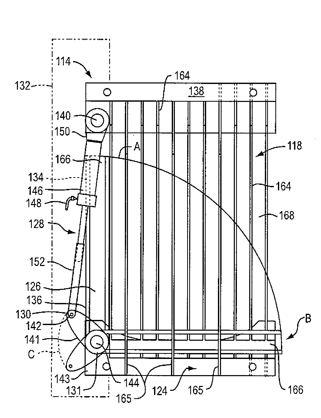
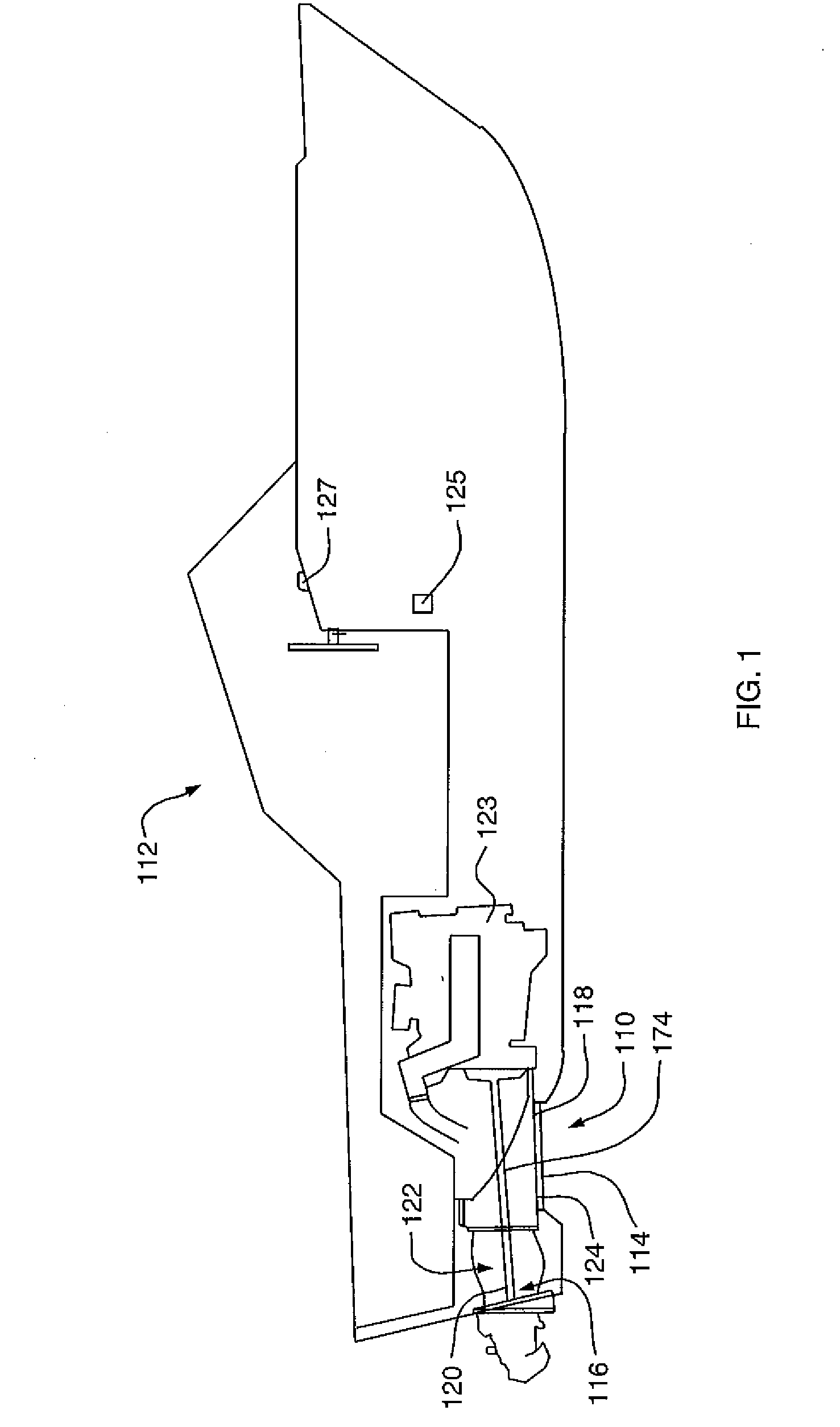
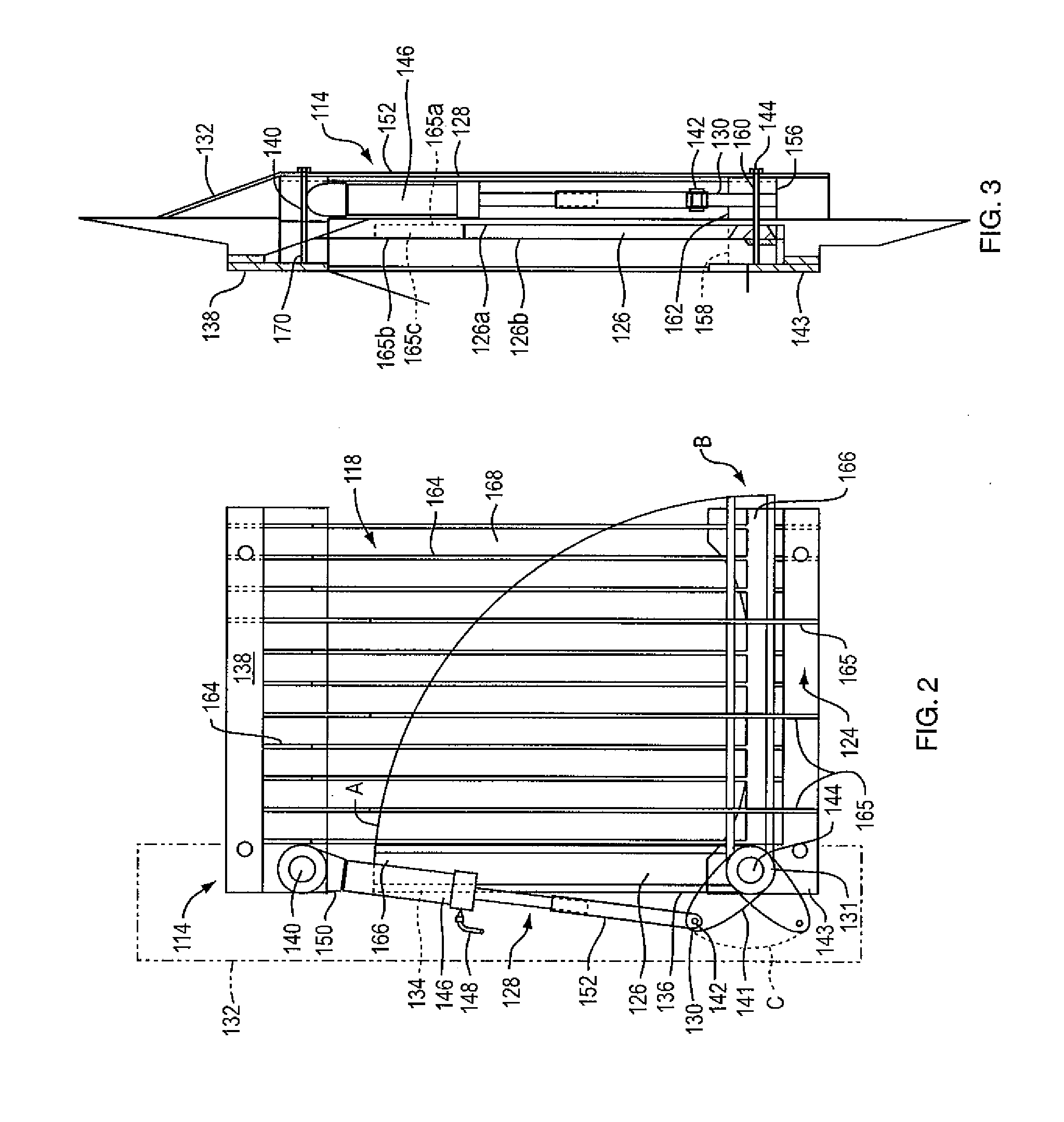
[0025]The present invention is a cutting system 110 for removing fouling such as seaweed, eel grass, or the like, from the intake grate of a water-jet drive system of a watercraft while the watercraft is stationary or is operating at any speed, including full speed. With reference to FIG. 1, the cutting system 110 is shown in position with respect to a watercraft 112. The cutting system 110 includes a cutter arm system 114 and, optionally, a cutter stud 116. The cutting system 110 is designed to cut away debris clogging an intake grate 118 and / or an impeller 120 within a housing 174 of the water-jet drive system 122. The water-jet drive system 122 is coupled to an engine 123. The cutter arm system 114 is coupled to a hydraulic pump 125 and is may be automatically actuated using a control switch 127. In one embodiment of the invention, the cutting system 110 includes the intake grate 118 having a frame 124. In this arrangement, the cutting system 110 includes a grate assembly to be d...


PUM


Abstract

A cutting system for fouling removal systems used in water-jet drive systems is described. The cutting system includes an actuation system for facilitating movement of a cutting blade that resides outside of the water flow area for the intake of the jet drive system. The cutting system also includes one or more guide tines to restrict movement of the cutting blade away from the surface of the grate. An optional cutter stud is formed as a single structure including two members forming a single angle, one member for mounting and the other for cutting. The single-angled configuration maximizes cutting efficiency while minimizing disruption of water flow to the propulsion system.

Description

CROSS REFERENCE TO RELATED APPLICATION[0001]The present application is related to U.S. patent application Ser. No. 11 / 769,972, filed Jun. 28, 2007, entitled “FOULING REMOVAL SYSTEM FOR JET DRIVE WATER INTAKE” of the same named inventor, from which application issued U.S. Pat. No. 7,377,826. The entire contents of that prior application and patent are incorporated herein by reference.BACKGROUND OF THE INVENTION[0002]1. Field of the Invention[0003]The present invention relates to systems for the removal of fouling materials such as seaweed and eel grass that can clog the intakes of jet drives. More particularly, the present invention relates to a cutting assembly arranged to resist separation from the intake grate of a jet drive. The present invention also relates to a cutting blade positioned adjacent to the impeller of the jet drive to provide improved cutting capability for the system to remove fouling from the jet drive impeller.[0004]2. Description of the Prior Art[0005]Watercraf...

Claims


Application Information

Patent Timeline
Patent Type & Authority Applications(United States)
IPC IPC(8): B63H11/01
CPCB63B59/04B63B2013/005B63H11/01
Inventor WENGREN, JR., RICHARD E.
Owner DJC MARINE TECH