Photoelectric conversion device and method for manufacturing the same
a technology of photoelectric conversion and conversion device, which is applied in the direction of solid-state devices, pv power plants, greenhouse gas reduction, etc., can solve the problems of bonding strength or mechanical strength likely to occur, and achieve the effect of increasing mechanical strength and controlling manufacturing costs
- Summary
- Abstract
- Description
- Claims
- Application Information
AI Technical Summary
Benefits of technology
Problems solved by technology
Method used
Image
Examples
embodiment 1
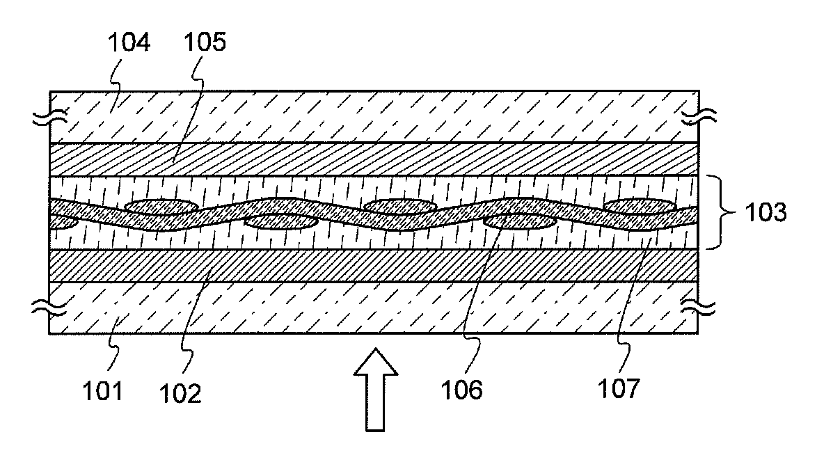
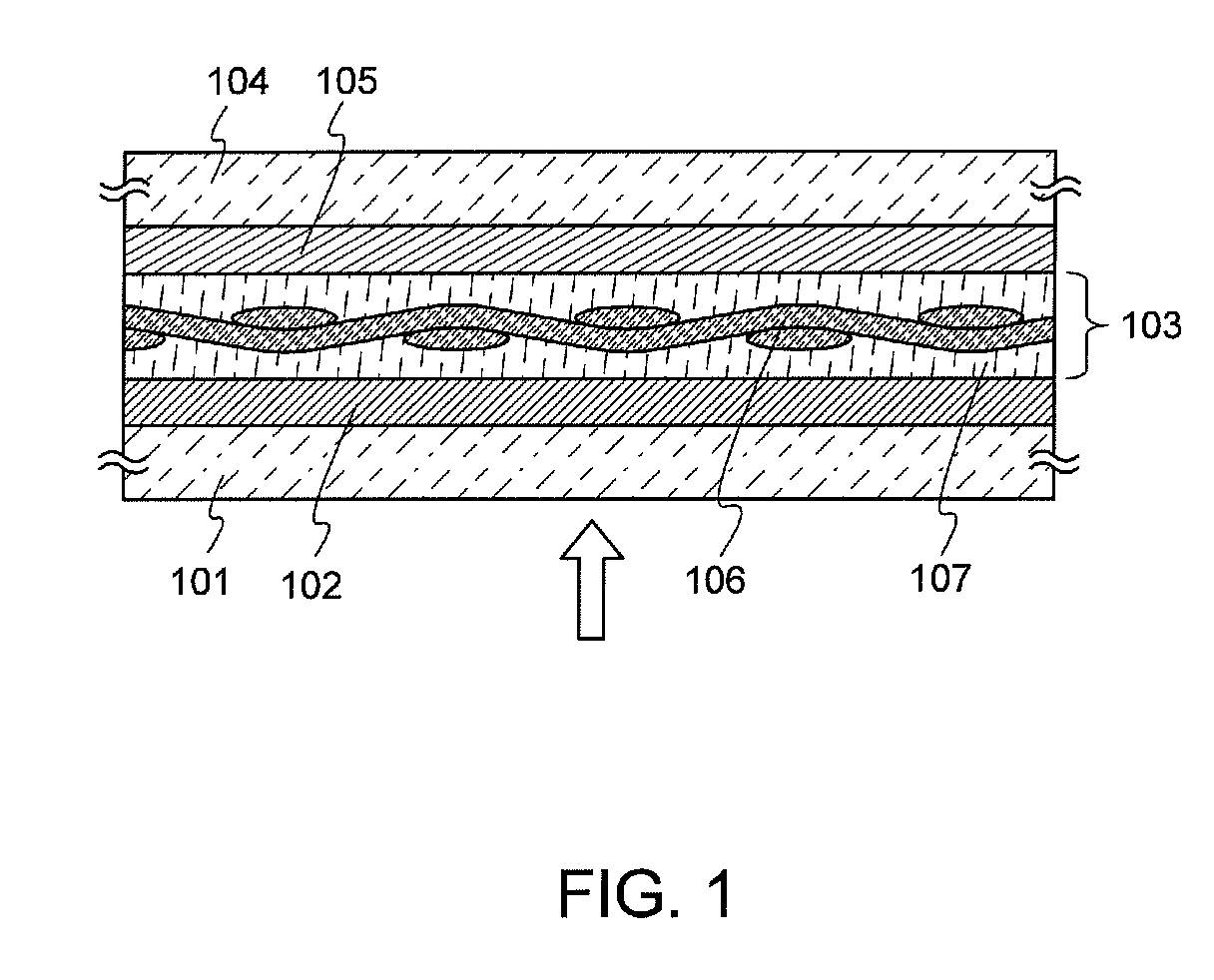
[0056]A photoelectric conversion device according to one embodiment of the present invention includes at least two cells. The cells each have a single-layer structure or a stacked-layer structure of a photoelectric conversion layer which is the minimum unit having a photoelectric conversion function. Further, the photoelectric conversion device has at least one structure body that is formed by impregnating a fiber body with a resin, which is interposed between the two cells. The structure of the photoelectric conversion device according to one embodiment of the present invention will be described with reference to FIG. 1.
[0057]A photoelectric conversion device illustrated in FIG. 1 includes a cell 102 (also referred to as a first cell) held by a substrate 101 (also referred to as a first substrate), a structure body 103, and a cell 105 (also referred to as a second cell) held by a substrate 104 (also referred to as a second substrate). The structure body 103 is interposed between th...
embodiment 2
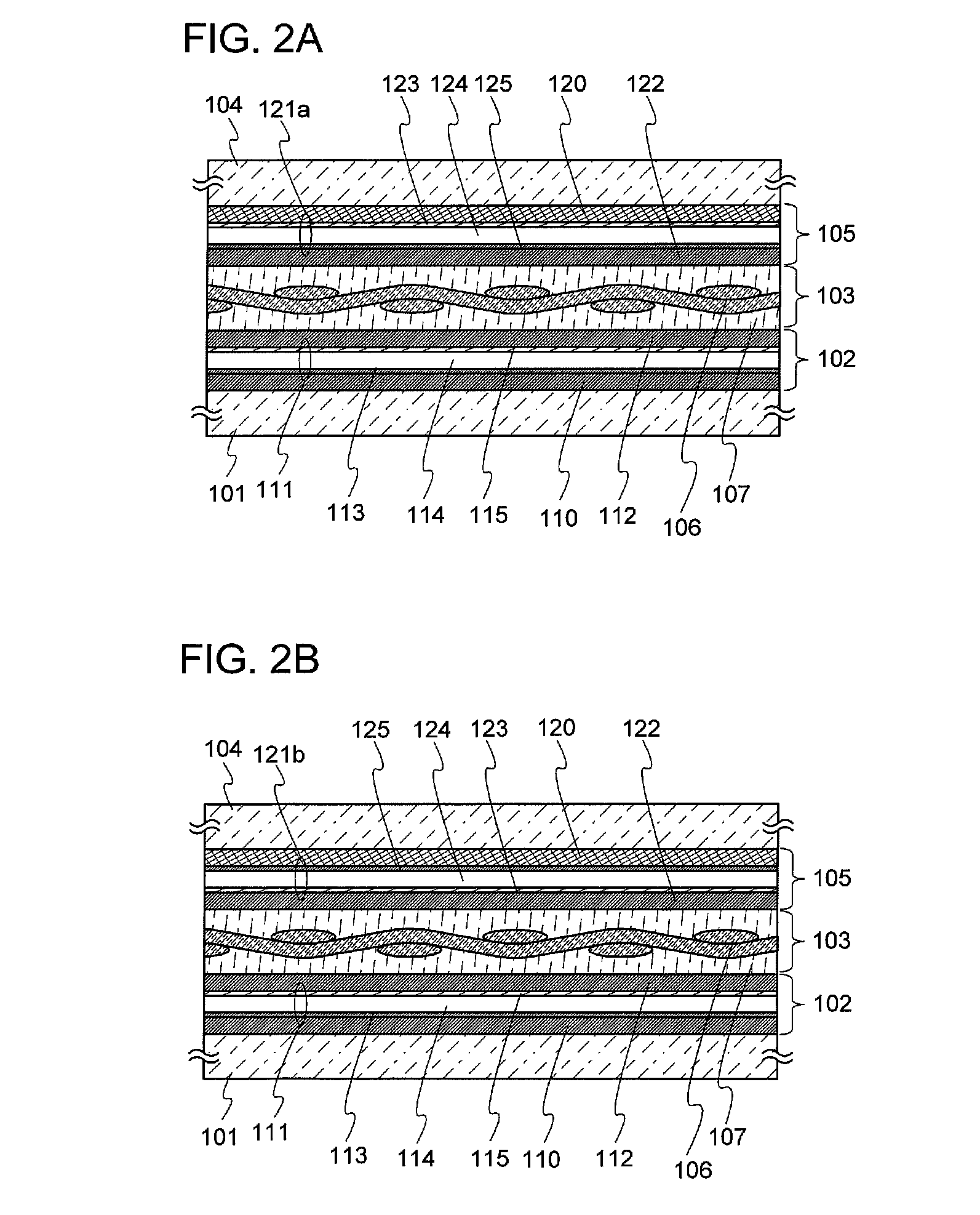
[0117]In this embodiment, a method for manufacturing the photoelectric conversion device of the disclosed invention will be described using the photoelectric conversion device illustrated in FIG. 2A as an example.
[0118]First, the formation of the cell 102 over the substrate 101 will be described. As illustrated in FIG. 6A, the conductive film 110 which is patterned (processed into a predetermined shape) is formed over the substrate 101. In this embodiment, since the photoelectric conversion device in which light enters from the substrate 101 side is described as an example, it is preferable that the substrate 101 have a property of transmitting visible light. As the substrate 101, for example, any of various commercial glass plates made of soda-lime glass, opaque glass, lead glass, tempered glass, ceramic glass, and the like can be used. Further, a non-alkali glass substrate of aluminosilicate glass, barium borosilicate glass, aluminoborosilicate glass, or the like; a quartz substra...
embodiment 3
[0162]In this embodiment, a structure in which a cell including a photoelectric conversion layer is formed over and adheres to a plastic substrate (a flexible substrate) will be described. Specifically, an example of the following structure will be described. In the structure, after a layer to be separated including a photoelectric conversion layer is formed over a supporting substrate having high heat resistance such as a glass substrate or a ceramic substrate with a separation layer and an insulating layer interposed therebetween, the supporting substrate and the layer to be separated are separated from each other using the separation layer, and the layer to be separated which is separated adheres to a plastic substrate to form a cell over the plastic substrate. In this embodiment, manufacture of a cell which is placed on the side opposite to the light incident side (a bottom cell) will be described. When a cell formed by a manufacturing method described in this embodiment is used...
PUM
 Abstract
Description
Claims
Application Information
 - R&D
- Intellectual Property
- Life Sciences
- Materials
- Tech Scout
- Unparalleled Data Quality
- Higher Quality Content
- 60% Fewer Hallucinations
Browse by: Latest US Patents, China's latest patents, Technical Efficacy Thesaurus, Application Domain, Technology Topic, Popular Technical Reports.
© 2025 PatSnap. All rights reserved.Legal|Privacy policy|Modern Slavery Act Transparency Statement|Sitemap|About US| Contact US: help@patsnap.com


