Method and device for the plasma treatment of running metal substrates

a metal substrate and plasma treatment technology, applied in plasma technique, plasma welding apparatus, manufacturing tools, etc., to achieve the effect of reducing surface resistance, reducing surface resistance, and minimizing losses by joule

Active Publication Date: 2010-12-09
NEOVAC GMBH
View PDF15 Cites 0 Cited by
  • Summary
  • Abstract
  • Description
  • Claims
  • Application Information

AI Technical Summary

Benefits of technology

[0013]The decontamination treatment of metal parts, following the ion bombardment of the surfaces of these, produces a high emission of atoms coming from the contamination layer removed, from which it is necessary to protect the inductor, which must preserve as small a surface resistance as possible, in order to minimise losses by Joule effect. The inductor is for example formed by a solenoid. In general, the inductor is made from copper and is advantageously coated on its surface with a deposit of silver in order to reduce its surface resistance as far as possible since the RF current flows essentially on the surface of the inductor.
[0028]Earthed shielding can advantageously be provided for protecting all the treatment device, to enable it to be fixed mechanically in the vacuum chamber, to provide the fixing of slings for manipulation thereof during maintenance and cleaning necessary after each production campaign, but also to reduce the RF emission in the vacuum chamber. In this case, precautions must be taken to prevent the formation of any stray plasma between this shielding and the inductor on the one hand and the electrode forming the Faraday screen on the other hand, but also current losses through movement by RF capacitive coupling to earth. The stray currents are reduced by maintaining sufficient space, at least several millimetres, between the internal surface of the shielding and the external surface of the inductor solenoid and, if necessary, with the flanges of the Faraday screen.

Problems solved by technology

The methods known up until now for cleaning or heating a metal product by plasma have several disadvantages:They make it possible to treat only metal surfaces, at most covered with a layer of metal oxide a few nanometres thick, and do not therefore make it possible to clean very highly oxidised products or those coated with polymers;These methods known from the prior art, based exclusively on the generation of a plasma by the emission of secondary electrons, are extremely propitious to the formation of electric arcs, which may make decontamination of the substrate very difficult, or even impossible, and even lead to an irremediable degradation of the surface of the latter by the formation of surface fusion points by dissipation of the energy of the arcs produced.The prior art allows only the treatment of metal substrates with simple geometric shapes, essentially longitudinal substrates with highly open surfaces passing right through the treatment devices.
This obviously limited this technology to the treatment of relatively thin sheets and strips in order to obtain a sufficiently intense magnetic field to allow the formation of a plasma by magnetron discharge in the vicinity of the surface opposite to the one behind which the arrays of magnets were disposed.
The device described in WO 02 / 12591, using at least one magnetic mirror that a longitudinal product must pass over, resolves this difficult but also has major drawbacks for a good number of practical applications.
This is because, though this device allows the treatment of elongate products of any shapes, such as girders with practically all cross sections, profiles, thin or thick sheets, tubes, wires, etc, in practice it again has certain drawbacks for the treatment of the ends of products that are long and which therefore do not pass right through the treatment device.
In this case, the magnetron discharge zone at the surface of the product to be treated, limited to the length of the substrate in the treatment area, may prove to be insufficient to form a stable plasma because of an axial confinement of the plasma that is insufficient in the direction of the magnetic mirror that the product does not pass over.
This does however greatly complicate the management of the system.
Another drawback of this device is that it is only with difficulty that it allows the treatment of products having greatly closed internal surfaces.
Thus, for example, this device allows the treatment of the entire surface of U-shaped, T-shaped or I-shaped girders, but presents more difficultly with the treatment of the internal surface of a partially closed U or a pipe split along its axis.
Another drawback of this device relates to the fact that the electrical characteristics of the plasma depend essentially on the geometric and surface characteristics of the substrate, which may create instabilities during the treatment in parallel of several substrates, such as for example girders passing in parallel in the treatment area.
Another drawback also occurs when a substrate is covered on certain areas with an electrically insulating material preventing the axial symmetry necessary to the functioning of the magnetron discharge described in WO 02 / 12591, and treatment of the part is then impossible.
A frequent drawback in practice of the devices and methods known up until now presents itself when the substrate is highly contaminated with a metal oxide.
In this case, the impossibility of independently controlling the flow of ions to the substrate and the discharge voltage promotes the formation of electric arcs, which greatly limits the useful power density, which may make it impossible to decontaminate a substrate without risk of damaging its surface with arc spots.

Method used


Image

  • Method and device for the plasma treatment of running metal substrates
  • Method and device for the plasma treatment of running metal substrates
  • Method and device for the plasma treatment of running metal substrates

Examples


Embodiment Construction

1. The Device According to the Invention:

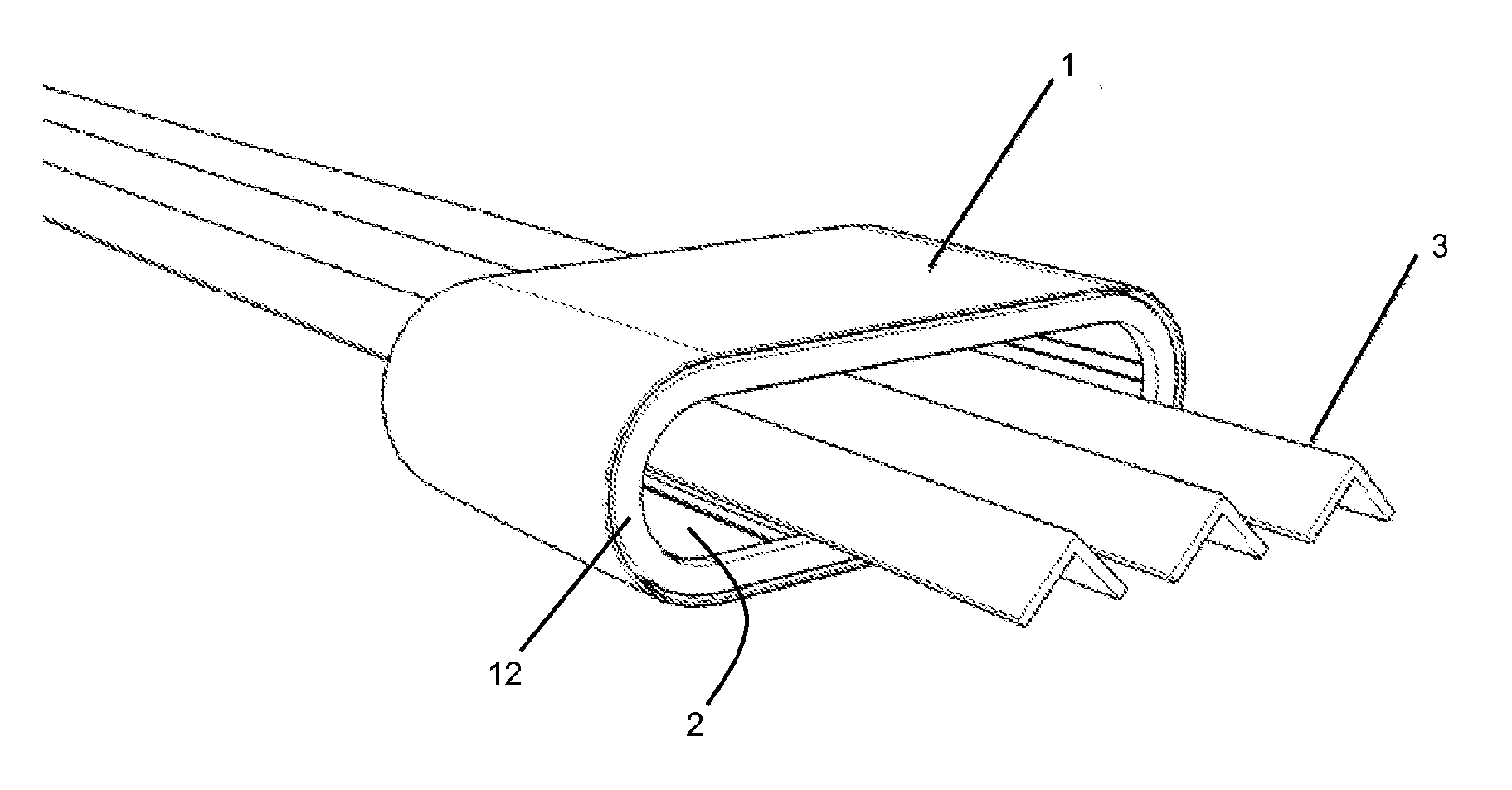
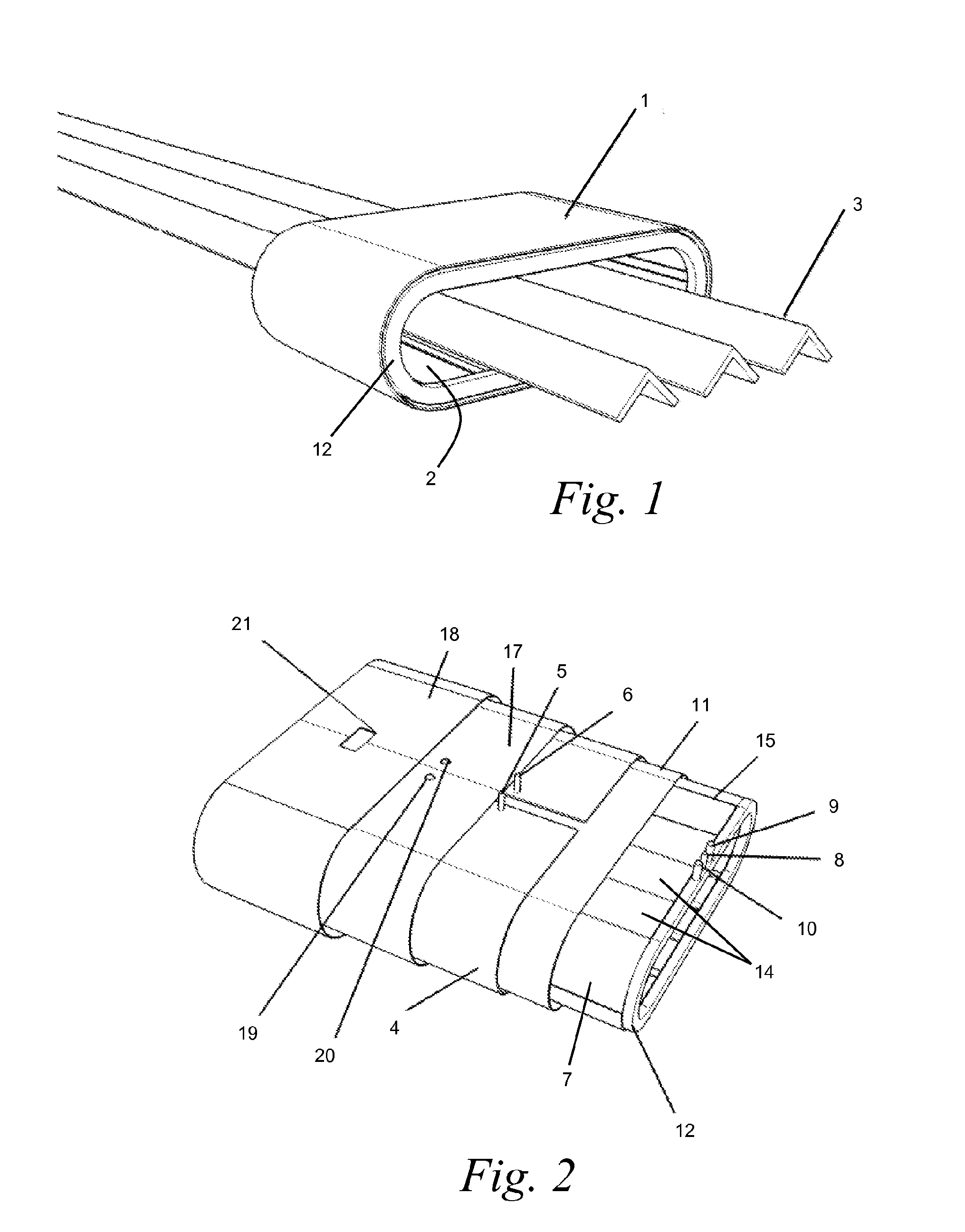
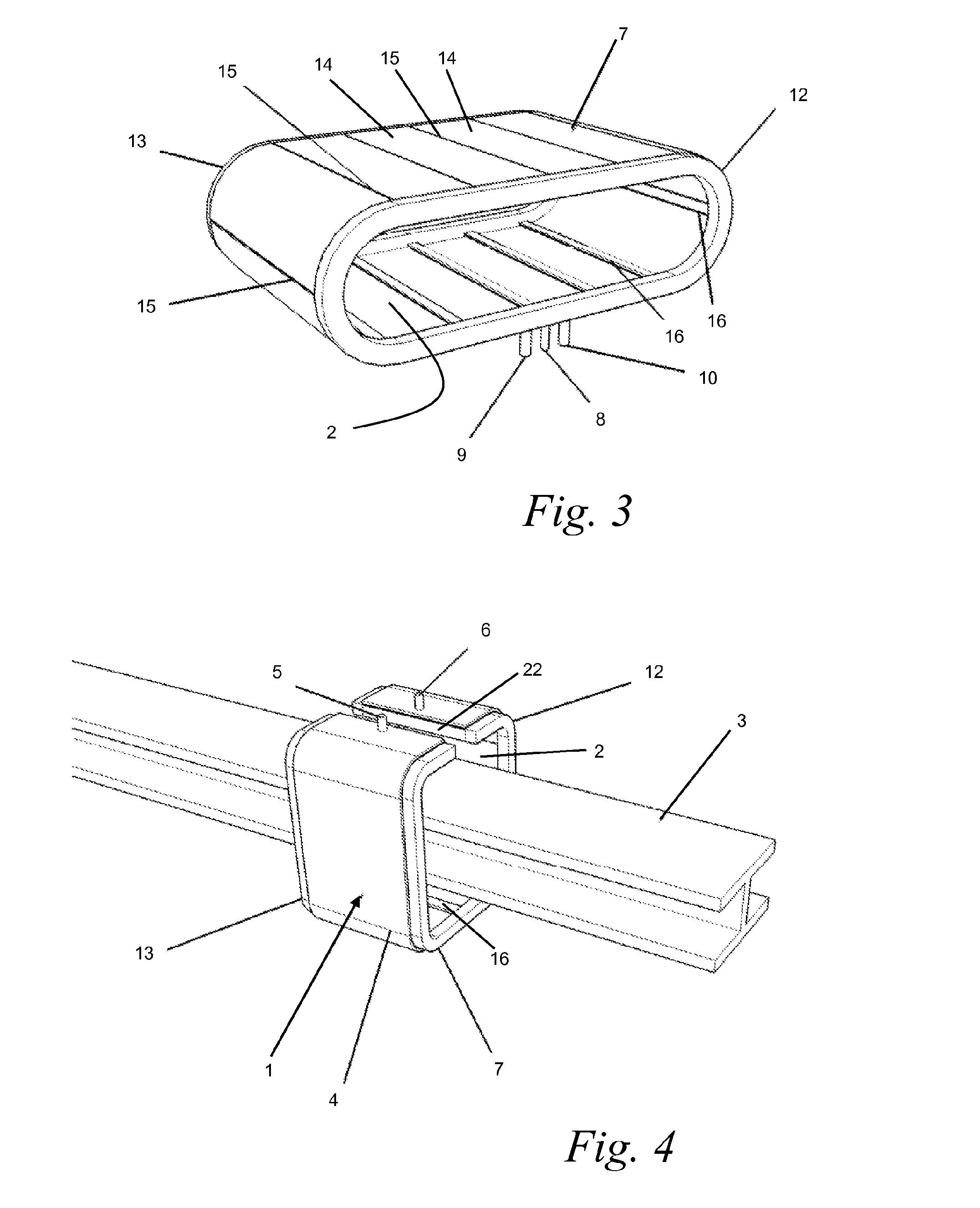
[0038]A device according to a particularly interesting embodiment of the invention is shown schematically in FIGS. 1 to 3. This device 1 is mounted in a vacuum chamber and comprises a treatment area 2 in which one or more metal substrates can travel substantially continuously. This treatment area 2 is situated inside the device.

[0039]In FIG. 1 a device is shown through which three metal girders 3 move, parallel to one another, in their longitudinal direction. The girders 3 are supported by banks of rollers, which are not shown in the figures, upstream and downstream of the treatment device.

[0040]The device has means for generating a plasma in the treatment area 2. These means comprise among other things an inductor 4 coupled to a radio-frequency generator for generating a plasma in the treatment area 2 by radio-frequency inductive coupling. The inductor 4, which at least partially surrounds the treatment area 2, is advantageously formed by a ...


PUM

PropertyMeasurementUnit
Distanceaaaaaaaaaa
Distanceaaaaaaaaaa
Distanceaaaaaaaaaa

Abstract

The invention relates to a method and a device for the plasma treatment of metal substrates or insulating substrates (3) running substantially continuously through a vacuum chamber having a treatment zone (2), the plasma being sustained by radiofrequency inductive coupling in the treatment zone (2) by means of an inductor (4) connected to a radiofrequency generator, in which the inductor (4) is protected from any contamination by the material emitted by the surface of the substrates (3) by means of a Faraday cage (7), which is positioned between the plasma and the inductor (4), and in which the Faraday cage (7) is on average electrically biassed positively with respect to the substrates (3) or with respect to a counter-electrode present in the plasma.

Description

[0001]The invention relates to a method for the plasma treatment, in particular cleaning and / or heating in mass production, of metal substrates or insulating substrates, in the form of wires, girders, tubes, plates, profiles, all types of transverse sections, strips and / or sheets, but also parts disposed on supports, for example metal hooks or baskets, transported in a treatment area by means of devices generally of any kind, such as a bank of rollers or a monorail transport system.[0002]In this method, the substrate to be treated is moved in a given direction in a vacuum chamber having a treatment area in which an electrical discharge is created between an electrode and a substrate, close to the surface of the latter, by means of a device that is also the subject matter of the invention.[0003]The method and device according to the invention make it possible in particular to eliminate a contamination layer on the substrate, such as a surface metal oxide and surface carbon, so as to ...

Claims


Application Information

Patent Timeline
IPC IPC(8): B23K10/00
CPCH01J37/32623H01J37/32697H01J37/32761H01J37/321C23F1/00H01L21/469H05H1/46
Inventor VANDENBRANDE, PIERRE
Owner NEOVAC GMBH
Why Eureka
Try Eureka