Micro rotor and rotary electric machine incorporating same

a rotary electric machine and micro-rotor technology, applied in the direction of dynamo-electric machines, magnetic circuits characterised by magnetic materials, electrical apparatus, etc., can solve the problems of low electric specific resistance of the magnet, failure to enable suppression of eddy current loss, and increase of magnetoresistance of radial gap type rotary electric machines including slotless iron cores, etc., to enhance the performance of various rotary electric machines, high output and low power consumption

Inactive Publication Date: 2010-12-09
MINEBEA CO LTD
View PDF7 Cites 14 Cited by
  • Summary
  • Abstract
  • Description
  • Claims
  • Application Information

AI Technical Summary

Benefits of technology

[0035]In order to achieve the object described above, according to another aspect of the present invention, there is provided a micro rotary electric machine, such as a slotless radial gap type brushless DC motor, a PM stepping motor or an electric generator, which incorporates the above described micro rotor. The rotary electric machines described above according to the present invention can be suitably used in inform

Problems solved by technology

However, a radial gap type rotary electric machine including a slotless iron core suffers an increase in magnetoresistance due to the gap.
Further, the electric specific resistance of the magnet is low, like nearly 10−5 Ωcm, thus failing to enable suppression of eddy current loss due to a high rotation speed.
Though the magnet of H. Kimura, et al has a higher remanence than the example reported by Topfer, T. Speliotis, et al, it is difficult for the radial gap type micro rotary electric machine incorporating the magnet of H. Kimura, et al. to achieve a torque equivalent to or higher than a torque produced by a comparable rotary electric machine incorporating the die-upset or sintered anisotropic magnet.
Furthermore, if epoxy resin is to be heated above the Curie Temperature of magnet material that exceeds the decomposition temperature of the epoxy resin, then not only the magnet material applicable must be limited, but also the mechanical strength of magnet deteriorates due to the carbonization of resin component to solidify the magnet material or eddy current loss is increased at a high rotation speed due to the decrease of electric specific resistance.
Consequently, the magnet of H. Kimura, et al. is not suitable as a micro rotor in terms of increasing a torque and also achieving an increased output by means of increasing the rotation speed.
(refer to Non-Patent Document 5) having a remanence Mr of 1.25 T, but the number of pole pair is limited to one and so it is impossible or extremely difficult for the magnet to be magnetized with a high permeance (B/μoH) and also to achieve a high electric specific resistance.
The torque of a rotary electric machine incorporating the above anisotropic magnet can be increased by enhancing the remanence Mr of the magnet, but such a rotary electric machine is disadvantageous in terms of increasing rotation speed due to S-T (Speed-Torque) drooping characteristic.
The magnet of D. Hinz et

Method used


Image

  • Micro rotor and rotary electric machine incorporating same
  • Micro rotor and rotary electric machine incorporating same
  • Micro rotor and rotary electric machine incorporating same

Examples


Embodiment Construction

s as well as Comparative Examples.

DETAILED DESCRIPTION OF THE INVENTION

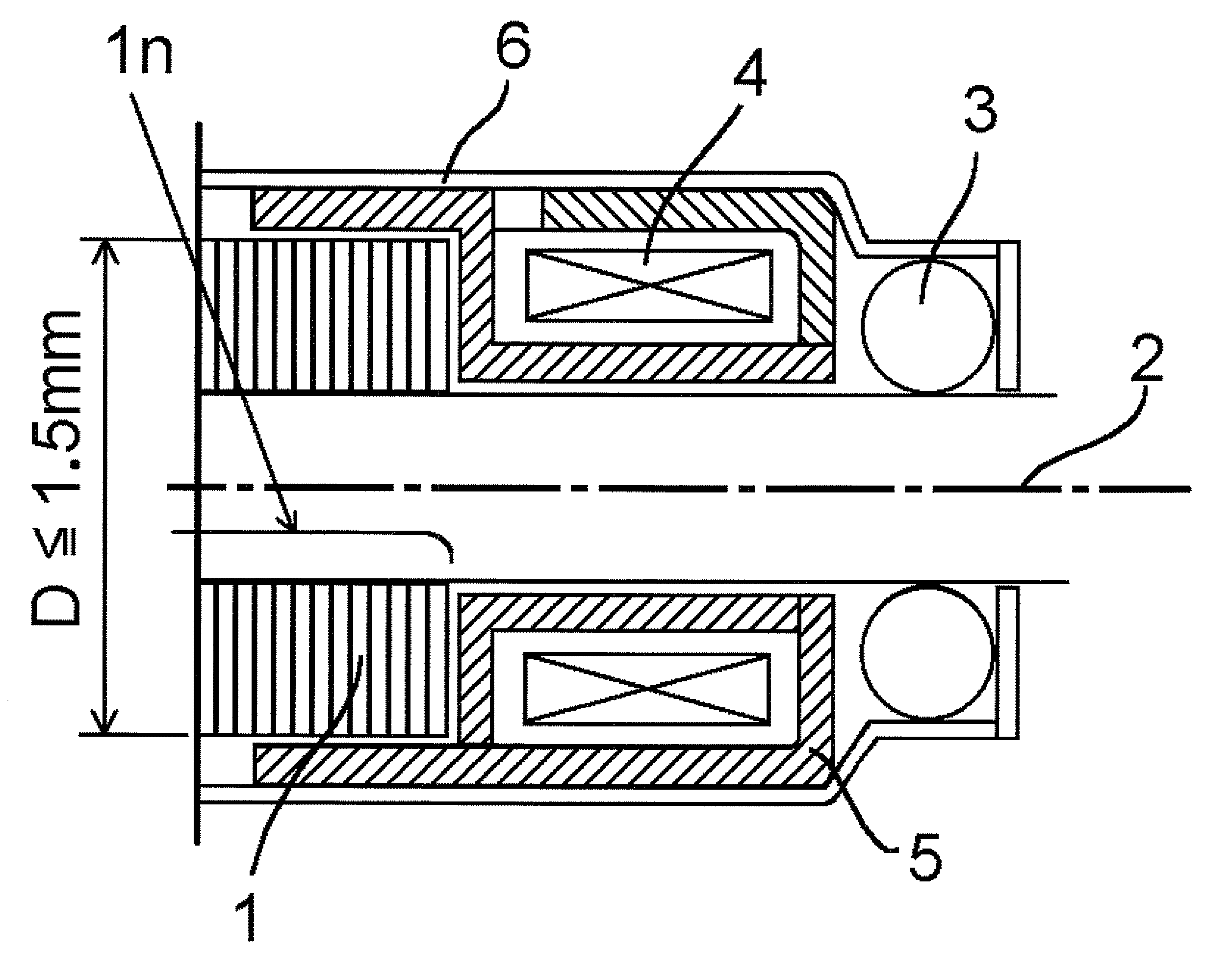
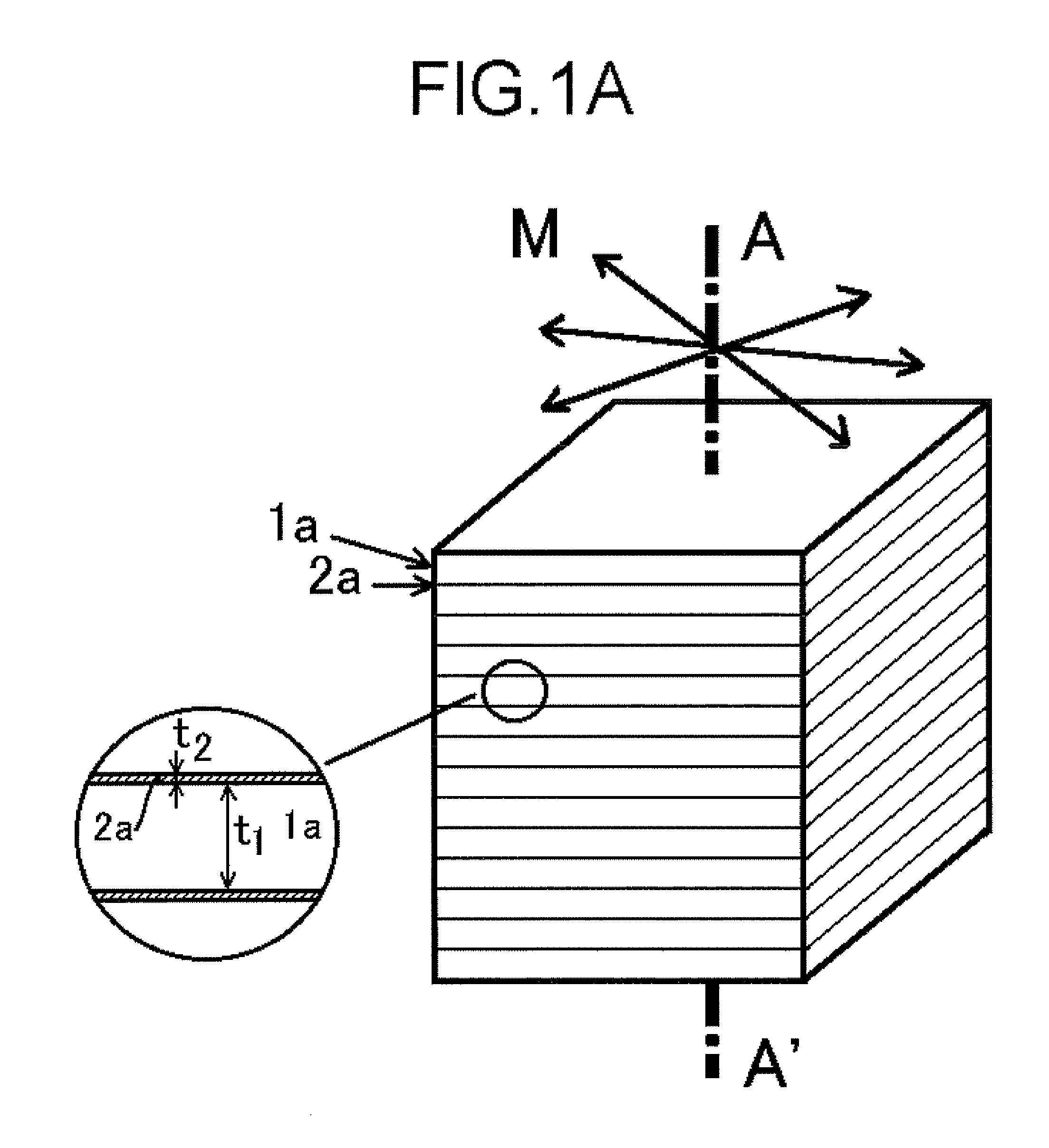
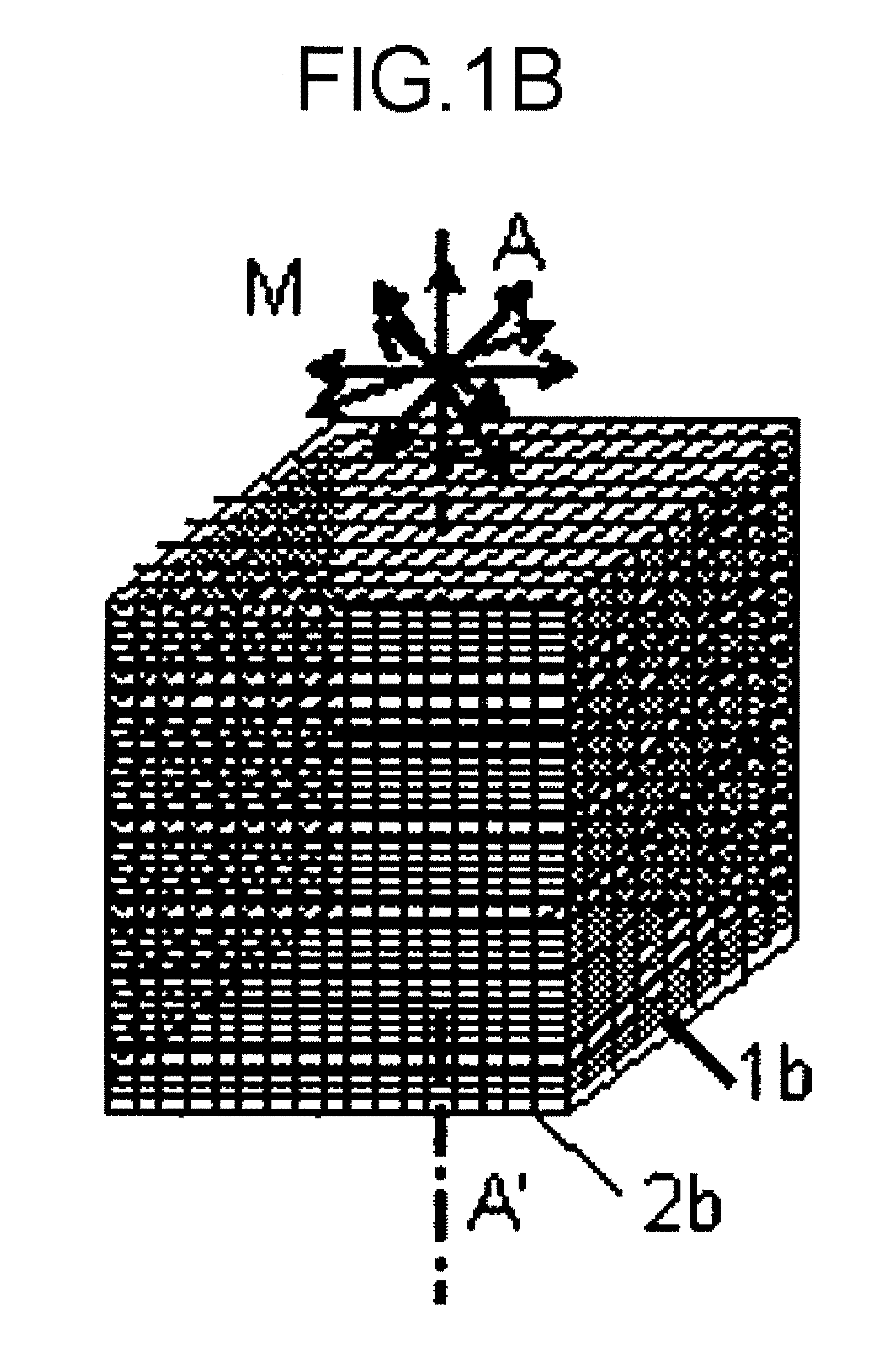
[0042]The present invention will be described with reference to the accompanying drawings. A detailed description will be made of an isolated lamination thick film magnet according to the present invention which is used as a micro rotor, has two or more pole pairs and includes a an in-plane direction mean magnetic path with a permeance (B / μoH) of five or more achieved by a magnet alone by itself, and which is structured such that a plurality of thick film magnets having a circular or annular plate shape are stacked on one another in the rotation axis rotation direction in a multilayer manner. Each of the thick film magnets includes an isotropic magnet with a thickness t1 having a remanence Mr of 0.95 T or more and a coercivity HcJ of 400 kA / m or more and a non-magnetic material with a thickness t2, provided for isolation between each adjacent two of the isotropic magnets, wherein the ratio of t1 / t2 is set at eigh...


PUM


Abstract

A micro rotor is disclosed and includes a plurality of circular or annular plate-shaped thick film magnets which each include an isotropic magnet with a thickness t1 having an in-plane remanence Mr of 0.95 T or more and a coercivity HcJ of 400 kA/m and a non-magnetic material with a thickness t2 adapted to isolate two adjacent isotropic magnets where the ratio of t1/t2 is eight or more and which are stacked on one another in multiple layers in the rotation axis direction, wherein at least two pole pairs are provided and a mean magnetic path of in-plane direction having a permeance (B/μoH) of five or more achieved by the magnet alone is provided, whereby eddy current is reduced. Also disclosed are a radial gap type brushless DC motor, a PM stepping motor and an electric generator which incorporate the above described micro rotor.

Description

BACKGROUND OF THE INVENTION[0001]1. Field of the Invention[0002]The present invention relates to a micro rotor, particularly to a micro rotor which is fabricated from an isolated lamination thick film magnet structured of multiple layers each layer including an isotropic magnet with a high remanence Mr and a non-magnetic material to isolate two adjacent isotropic magnets, which has a pole pair number of two or more and which includes a mean magnetic path of in-plane direction having a permeance (B / μoH) of five or more achieved by the magnet alone, and further relates to a rotary electric machine which incorporates such a micro rotor.[0003]2. Description of the Related Art[0004]A rotary electric machine for application in, for example, the field of information and telecommunication devices has been commercially produced with its volume reduced to about 100 mm3 and is widely used. Such a rotary electric machine is requested to be further downsized in order to reduce the size, thicknes...

Claims


Application Information

Patent Timeline
IPC IPC(8): H02K21/14
CPCH02K1/02H02K21/125H02K1/2733
Inventor YAMASHITA, FUMITOSHINISHIMURA, SHINSAKUMENJO, NOBORU
Owner MINEBEA CO LTD
Why Eureka
Try Eureka