Method for determining the angular position of the rotor of a mechanically commutated dc servo motor

Active Publication Date: 2010-12-16
CONTINENTAL AUTOMOTIVE GMBH
View PDF5 Cites 5 Cited by
  • Summary
  • Abstract
  • Description
  • Claims
  • Application Information

AI Technical Summary

Benefits of technology

[0007]A basic concept of the invention is to carry out an analysis of the current ripple on the basis of a metrologically determined contact bounce time interval, during a time interval in which an analysis of the current ripple based on disturbances in the armature current signal is not possible. The rotor position can be determined with greater accuracy by this adaptation of the analysis process to the actual bounce time of a changeover relay. During the programming of an analysis algorithm, it is not necessary to use an a-priori probability of a worst-case (longest) bounce time as a basis, but instead the analysis time adapts to the ageing and to the prevailing operating status of the changeover relay. In other words, the imprecision of an analysis process, which is naturally present, is used according to the invention only as long as it is actually necessary. This improves the positional accuracy.
[0008]During a closing operation more accurate information on the position, and therefore also on the starting position, of the closing part is present. The effect of a jamming protection of a motor-driven closing part is therefore improved. This advantage is decisive, especially for a window lifter in the area of approximately 4 mm before entry into the frame seal. Thanks to the invention, the risk of injury can be largely minimized in this case. On the other hand, a secure closure is also achieved.
[0009]A further essential advantage can be seen in that the cumulative error when determining the position is less even during frequent changes in direction of rotation and where there is backlash in the drive train. This means that the drive system needs to be initialized less frequently. The consequence of this is that the availability of the system is increased because, unlike previously, it is not necessary to limit various functions, such as the automatic operation of a window lifter, due to accumulative errors.
[0013]In a further preferred embodiment, it can be provided that a start time point can be determined from a control signal generated by the control and analysis unit and fed back to the switching device and an end time point of the contact vibration time interval can be determined from a first or second contact voltage feedback signal assigned to this time signal. The advantage of this is that only the end of the contact vibration time interval has to be measured, with the start being preset by the control system. In this way, the analysis is simpler overall but this is at the cost of accuracy because the analysis process is also used during the response time of a relay, but in this case an evaluation, i.e. counting, of the current ripple would still be possible.
[0015]The accuracy of the position determination can be further improved if the analysis algorithm, as an extension to a stored drive model, can also take account of the rotational speed of the rotor before the changeover of a switching contact.
[0016]A feedback circuit, which is often already present in existing motor vehicle servodrives for monitoring relay contacts, is advantageous. A change to the hardware is not necessary.

Problems solved by technology

In operating phases in which the d.c. servo motor is started, braked or its operation is reversed, a determination of the current ripple is, however, difficult because contact or relay bounce occurs during the switchover of the mechanical contacts.
During a time segment, referred to in the following as a contact bounce time interval, the armature current signal is disturbed and a direct analysis of the current ripple is not possible.
With an electrically operated motor vehicle window lifter or sunroof, the zero position can shift because of this effect, which is further aggravated by backlash in the drive train.
If, however, a closing operation of a window or sunroof starts from a position which is associated with imprecision, then in the event of jamming this can cause the maximum permissible closing force to be exceeded.
Due to the inexact information with regard to the position, injuries can occur due to the trapping of body parts.
To prevent this, the servodrive has to be frequently initialized, which is disadvantageous.

Method used


Image

  • Method for determining the angular position of the rotor of a mechanically commutated dc servo motor
  • Method for determining the angular position of the rotor of a mechanically commutated dc servo motor
  • Method for determining the angular position of the rotor of a mechanically commutated dc servo motor

Examples


Embodiment Construction

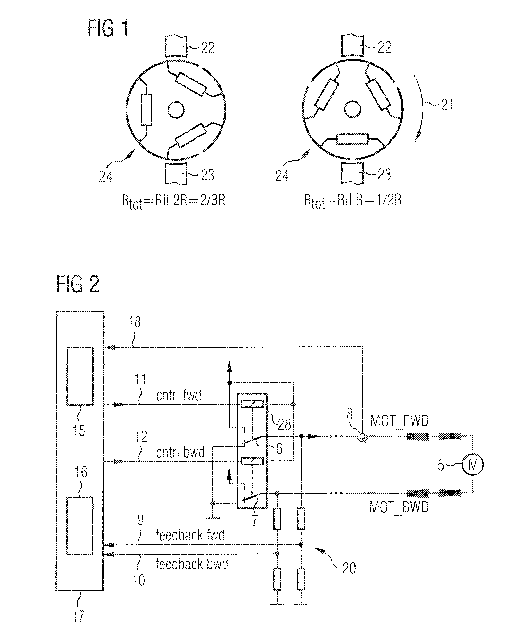
[0026]FIG. 1 is a schematic representation showing the resistance relationships during a mechanical commutation operation of a d.c. motor. The collector 24 consists of three collector segments. The armature coils are shown by three ohmic resistors. As can be seen from the left-hand sketch in FIG. 1, an ohmic resistor, formed by a parallel circuit, is positioned between both brushes 22, 23, with the left-hand resistor being positioned in parallel with two resistors arranged in series. During a rotation of the collector (arrow 21), which is shown in the right-hand part of FIG. 1, the bottom brush 23 passes over two adjacent collector segments. This briefly causes a short circuit between these adjacent collector segments. The ohmic resistance between both brushes 22, 23 in this time instant is formed by a parallel circuit consisting of two coil resistors. This change in resistance is accompanied by the armature current ripple mentioned in the introduction, so that the rotor position ca...


PUM


Abstract

Method for determining the angular position of the rotor of a mechanically commutated DC servo motor (5), which is arranged in the transverse branch of a bridge circuit, and the armature current of which is preset by an electromechanically activated switching device (28), —with a control and analysis unit (17) which analyzes the current ripple (3) present in the armature current (2) and attributable to the mechanical commutation, characterized in that—from each switch contact (6, 7) of the switching device (28), a contact-voltage feedback signal (9, 10) is fed back to the control and analysis device (17) by means of a feedback circuit (20), and in that the control and analysis unit (17), by using the at least one contact-voltage feedback signal (9, 10), determines a contact vibration time interval (4) and performs an estimate of current ripple (3) during this contact vibration time interval (4), during which an analysis of the current ripple due to contact vibrations which are caused by a switching process of at least one of the switch contacts (6, 7) is not possible.

Description

TECHNICAL FIELD[0001]The invention relates to a method for determining the angular position of the rotor of a mechanically commutated d.c. servo motor, whose armature current is preset by a switching state of an electromechanically actuated switch contact, with a current ripple, present in the armature current and attributable to the mechanical commutation, being analyzed by a control and analysis unit.PRIOR ART[0002]For servo drives, such as used in vehicles, for example for operating window lifters and sunroofs, mechanically commutated d.c. servo motors are used. The d.c. servo motor is arranged in a circuit in a shunt arm of a bridge circuit in which two switching contacts of a relay, controlled by a microcontroller, preset the direction of the motor current. In order to limit the closing force during a closing operation, the current position of the closing part must be known by the microcontroller.[0003]It is known that the rotor position can be directly determined by analyzing ...

Claims


Application Information

Patent Timeline
IPC IPC(8): G05D3/12
CPCH02P7/0094H02P7/20
Inventor CROCOMO, LEANDROKOLLNER, WOLFGANGMORAWEK, ROMANPOZZER, ALEXANDRE
Owner CONTINENTAL AUTOMOTIVE GMBH
Why Eureka
Try Eureka