Frequency synthesis

a frequency synthesiser and frequency technology, applied in the direction of oscillation generators, electric long antennas, antennas, etc., can solve the problems of deteriorating receiver performance, or more importantly transmit spectrum, affecting the performance of receivers, etc., to achieve high precision frequency control, simple phase control, and optimise loop performance

Inactive Publication Date: 2010-12-23
NXP BV
View PDF13 Cites 38 Cited by
  • Summary
  • Abstract
  • Description
  • Claims
  • Application Information

AI Technical Summary

Benefits of technology

[0033]Optionally, the frequency synthesiser may comprise a phase estimator for generating a first indication of the phase of the first oscillator signal, and the second variable frequency oscillator may be adapted to provide a second indication of the phase of the second oscillator signal, and the phase difference generator may be adapted to employ the first and second indications for generating the phase difference signal. Thus indications of the phases of the first and second oscillator signals may be provided separately, which provides a useful degree of freedom in embodiments of the invention, in particular flexibility in generating independently the frequencies required for transmit and receive in a time division duplex system.
[0034]Optionally, the controller may comprise at least one of a first filter for filtering the first control signal and a second filter for filtering the second control signal. Thus different time constants may be applied to the first and second control signals, enabling optimisation of loop performance.
[0035]Op...

Problems solved by technology

In addition there will be capacitance contributed by the active circuit and layout parasitics.
In this process, which is often described as dithering, and known per se f.i. from U.S. Pat. No. 5,036,294 the capacitor hopping introduces an undesirable oscilla...

Method used


Image

  • Frequency synthesis
  • Frequency synthesis
  • Frequency synthesis

Examples


Embodiment Construction

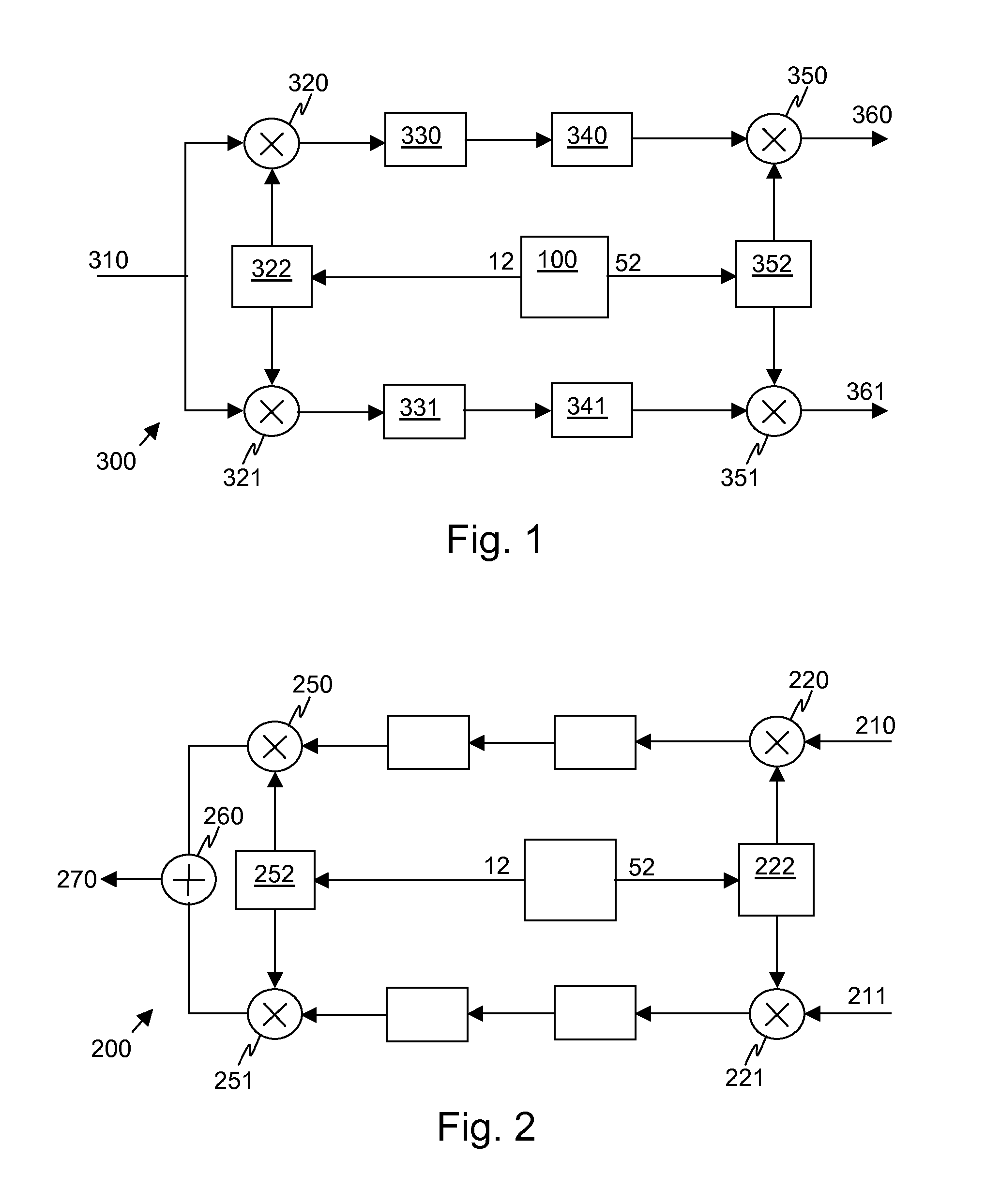
[0047]Referring to FIG. 1, there is illustrated a receiver comprising an input 310 for an RF received signal provided by a non-illustrated antenna. The input 310 is coupled to mixers 320, 321 for multiplying the RF received signal by respective quadrature components of an RF local oscillator signal. A first oscillator signal is provided by an output 12 of a frequency synthesiser 100 to a divider 322 which divides the first oscillator signal and provides the quadrature components of the RF local oscillator signal to the mixers 320, 321. The frequency of the first oscillator signal may be twice the required frequency of the RF local oscillator signal, in which case the divider 322 divides by two. This division ratio conveniently enables the quadrature components to be derived in a simple manner, although other ratios may alternatively be used.

[0048]Respective outputs of the mixers 320, 321 provide IF analogue I and Q signals, and these outputs are coupled to respective low-pass filter...


PUM


Abstract

A frequency synthesiser (100) has a first variable frequency oscillator (10) for generating a first oscillator signal having a frequency responsive to a first control signal, a second variable frequency oscillator (50) for generating a second oscillator signal having a frequency responsive to a second control signal, and a phase reference generator (40) for generating a phase reference signal. There is a phase difference generator (30) for generating a phase difference signal indicative of the phase difference between the sum of the phases of the first and second oscillator signals and the phase of the phase reference signal. A controller (60) responsive to the phase difference signal generates the first and second control signals. At least one of the first and second control signal are determined dependent on a value of the phase difference signal, and at least one of them are determined dependent on a further characteristic of a signal, the further characteristic being supplementary to the effect of any dithering introduced into the frequency synthesiser (100).

Description

FIELD OF THE INVENTION[0001]The invention relates to a frequency synthesiser, a wireless transmitter and receiver comprising a frequency synthesiser, and a method of frequency synthesis.BACKGROUND OF THE INVENTION[0002]Architectures for wireless transmitters and receivers commonly require the generation of reference signals at two frequencies, a radio frequency (RF) signal at a carrier frequency and an intermediate frequency (IF) signal at a lower frequency.[0003]For example, the well-known “near-zero IF” radio receiver architecture used in cellular telephones, cordless telephones, and connectivity applications, converts a received RF signal to a frequency close to DC by mixing the received signal with quadrature local oscillator signals in two parallel signal paths. Nominally the IF is set to a fixed frequency offset, for instance related to the channel spacing. Such a frequency choice enables relaxation of image rejection requirements for demodulation implemented within subsequent...

Claims


Application Information

Patent Timeline
IPC IPC(8): H04B1/04H04B1/26H03B21/00
CPCH03L7/0994H03L7/085
Inventor RIDGERS, TIMOTHY JOHN
Owner NXP BV
Why Eureka
Try Eureka