Oil water separation apparatus

a technology of oil water separation and oil water tank, which is applied in the direction of separation process, wellbore/well accessories, liquid displacement, etc., can solve the problems of inability to add sufficient quantities of solvent to make it possible to process oil-water, the complexity of oil-water separation facilities, and the inability to process oil-water

Inactive Publication Date: 2010-12-30
GENERAL ELECTRIC CO
View PDF14 Cites 38 Cited by
  • Summary
  • Abstract
  • Description
  • Claims
  • Application Information

AI Technical Summary

Problems solved by technology

The complexity of oil-water separation facilities depends upon the form of the water found in association with the oil.
Particularly in the case of water-in-oil emulsions in which the water phase is dispersed in very small droplet form, such emulsions can often times be broken only with difficulty.
However, despite the fact that the method and apparatus have been found to be extremely effective for separating the oil in an oil-water mixture, it has been found that in some instances, particularly when dealing with oils having extremely high viscosity residual oil fractions, it can be impractical to add sufficient quantities of solvent to make it possible to process an oil-water mixture in an oil-water coalescer.
In addition, in some instances it may be impractical to carry sufficient quantities of solvent on board a marine vessel operating on the surface of a body of water in order to process an oil-water mixture containing a high viscosity residual oil fraction in a continuous on-board operation wherein separated water is returned to the body of water.
The process may be slow and at times not effective for the separations of an emulsion into its components.
However, such additives have to be removed from the separated oil, leading to additional production costs.
The large tanks required for gravity separation in deep water are disfavored due to their weight and logistical challenges associated with the installation and operation of a massive subsea structure.

Method used


Image

  • Oil water separation apparatus
  • Oil water separation apparatus
  • Oil water separation apparatus

Examples


example 1

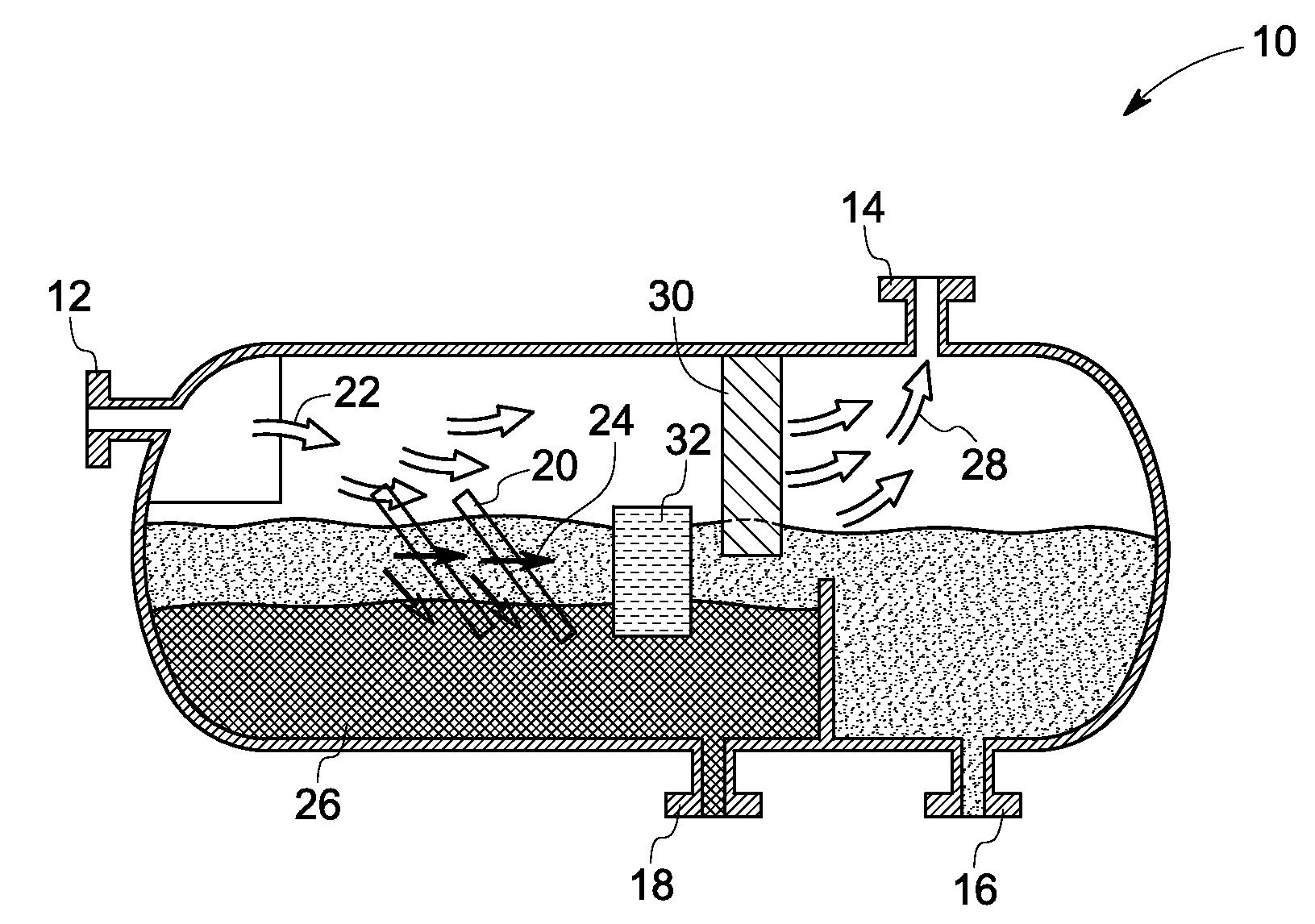
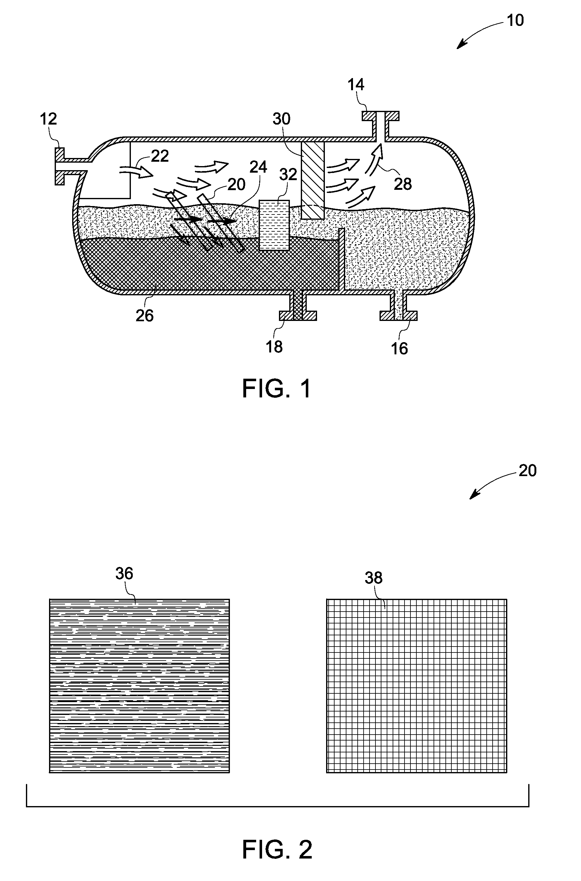
[0041]A 1 meter by 1 meter stainless steel mesh screen having an average pore size of about 1 cm by 1 cm and a mesh thickness of about 0.25 cm is treated with a hot solution of linear low density poly(ethylene) (LLDPE) in xylene-ethanol in an amount sufficient to coat the mesh surfaces while leaving the pores open. The coating of LLDPE on the stainless steel is superhydrophobic and oleophilic. A plurality of such treated mesh screens is then disposed within the flow path of a subsea separation vessel.

example 2

[0042]A cyclic separator comprising an interior surface made of LLDPE is attached to a source of hot (120° C.) xylene. Hot xylene is passed through the cyclonic separator over a period of time ranging from about 1 minute to about 10 minutes. The feed of hot toluene is discontinued and immediately thereafter a hot mixture of xylene and ethanol (1:1) is recirculated through the cyclonic separator. Heating of the recirculating mixture of xylene and ethanol is discontinued and recirculation is continued until the temperature of the xylene-ethanol mixture reaches ambient temperature. The treated interior surface of the cyclonic separator is superhydrophobic and oleophilic.

example 3

[0043]The inner tube of a concentric tube separator constructed of LLDPE is immersed in hot xylene for a period ranging from about 1 minute to about 10 minutes. A volume of ethanol equal to the volume of xylene is then added and the bath is allowed to cool to ambient temperature. The inner tube of the concentric separator is then disposed within the outer tube of the concentric separator and the concentric separator is disposed within the flow path of a subsea separation vessel. The surfaces of the treated inner tube of the concentric tube separator is superhydrophobic and at least oleophilic.


PUM

PropertyMeasurementUnit
contact angleaaaaaaaaaa
oil contact angleaaaaaaaaaa

Abstract

In one aspect, the present invention provides a subsea separation vessel for the separation of a mixture comprising oil and water comprising (a) at least one inlet for introducing a oil-water mixture; (b) a flow path for conducting the oil-water mixture; (c) at least one oil-water separation structure; and (d) at least one fluid outlet. The oil-water separation structure includes a multifunctional surface. The oil-water separation structure is located within the flow path and wherein the multifunctional surface is superhydrophobic with respect to water, and either oleophilic or superoleophilic with respect to oil. A method for separating oil from an oil-water mixture is also provided.

Description

BACKGROUND[0001]The invention relates to a subsea oil-water separation vessel. In addition, the present disclosure relates to a method for separating oil from an oil-water mixture.[0002]There are various industrial applications in which it is desirable to separate the oil and water phases of a fluid stream into discrete components. In the petroleum industry, crude oil recovered from wells penetrating subterranean oil-bearing formations is usually accompanied by water. Since the crude oil when it is sold to a pipeline or other transportation facility should be substantially free of water, e. g. have a water content of less than 1 or 2% by volume, it becomes necessary to provide for dehydration of the oil at the field processing facility associated with the production wells.[0003]The complexity of oil-water separation facilities depends upon the form of the water found in association with the oil. Where the water present in the production stream is substantially “free water”, the oil ...

Claims


Application Information

Patent Timeline
Patent Type & Authority Applications(United States)
IPC IPC(8): B01D17/022B01D17/02B01D19/00B01D17/04
CPCB01D17/0211E21B43/36C10G33/06C10G33/04
Inventor VARANASI, KRIPA KIRANKULKARNI, AMBARISH JAYANTWOLFE, CHRISTOPHER EDWARD
Owner GENERAL ELECTRIC CO
Why Eureka
Try Eureka