Electricity generator

a technology of electric generators and generators, applied in the direction of electric generator control, machine/engine, etc., can solve the problems of inability to meet the requirements of voltage and frequency control, one or more limitations of introduction, cost, complexity, efficiency and reliability, etc., and achieve the effect of minimal cost and difficult reliably control

Active Publication Date: 2010-12-30
OXFORD UNIV INNOVATION LTD
View PDF61 Cites 15 Cited by
  • Summary
  • Abstract
  • Description
  • Claims
  • Application Information

AI Technical Summary

Benefits of technology

[0018]Although, in a most general sense, aspects of the present invention provide for a fixed capacitance and resistance, in a preferred embodiment, at least the capacitance, and most preferably the resistance of the load as well, is variable. This allows the generator to provide maximum or near maximum power output across a wider range of wind speeds incident upon the turbine.
[0019]In particular, in order to optimise the power generated by the generator for various wind speeds, embodiments of the present invention optimally run at the designed tip speed ratio (TSR) under a range of wind conditions. This in turn implies that the turbine / generator rotational speed must vary substantially linearly with wind speed. Preferred embodiments of the present invention thus employ a variable transmission. Although a mechanical variable ratio gearbox could be employed, such devices are expensive, costly and difficult reliably to control. As a further consequence of the arrangements of preferred embodiments of the present invention, by contrast, where a transmission is employed, it may be implemented electrically and at minimal cost and in silence. Again, this is in part a consequence of the shift away from the control of voltage and frequency.

Problems solved by technology

The bulk of the prior art discussed in the introduction suffers from limitations of one or more of cost, complexity, efficiency and reliability.
In the main, these drawbacks are a consequence of the perceived need to control the generator output voltage and / or frequency, which requires accurate regulation of the reactive excitation current and / or prime mover torque.
In fact, the intermittent nature of wind power means that applications that require controlled voltage and frequency are inherently unsatisfactory anyway, in the sense that either expensive and inefficient electrical storage, or costly and inefficient electronics to inject the power into the national grid, is necessary.

Method used


Image

  • Electricity generator
  • Electricity generator
  • Electricity generator

Examples


Embodiment Construction

[0041]Before describing a preferred implementation of the present invention, a brief review of the theoretical principles of induction generators (and in particular, self excited induction generators) is appropriate, since this will assist in an understanding of the particular approach taken—specifically, the reasons why it is beneficial, in the present application, to set aside the requirement to control voltage, frequency and / or prime mover torque.

Ideal Induction Generator

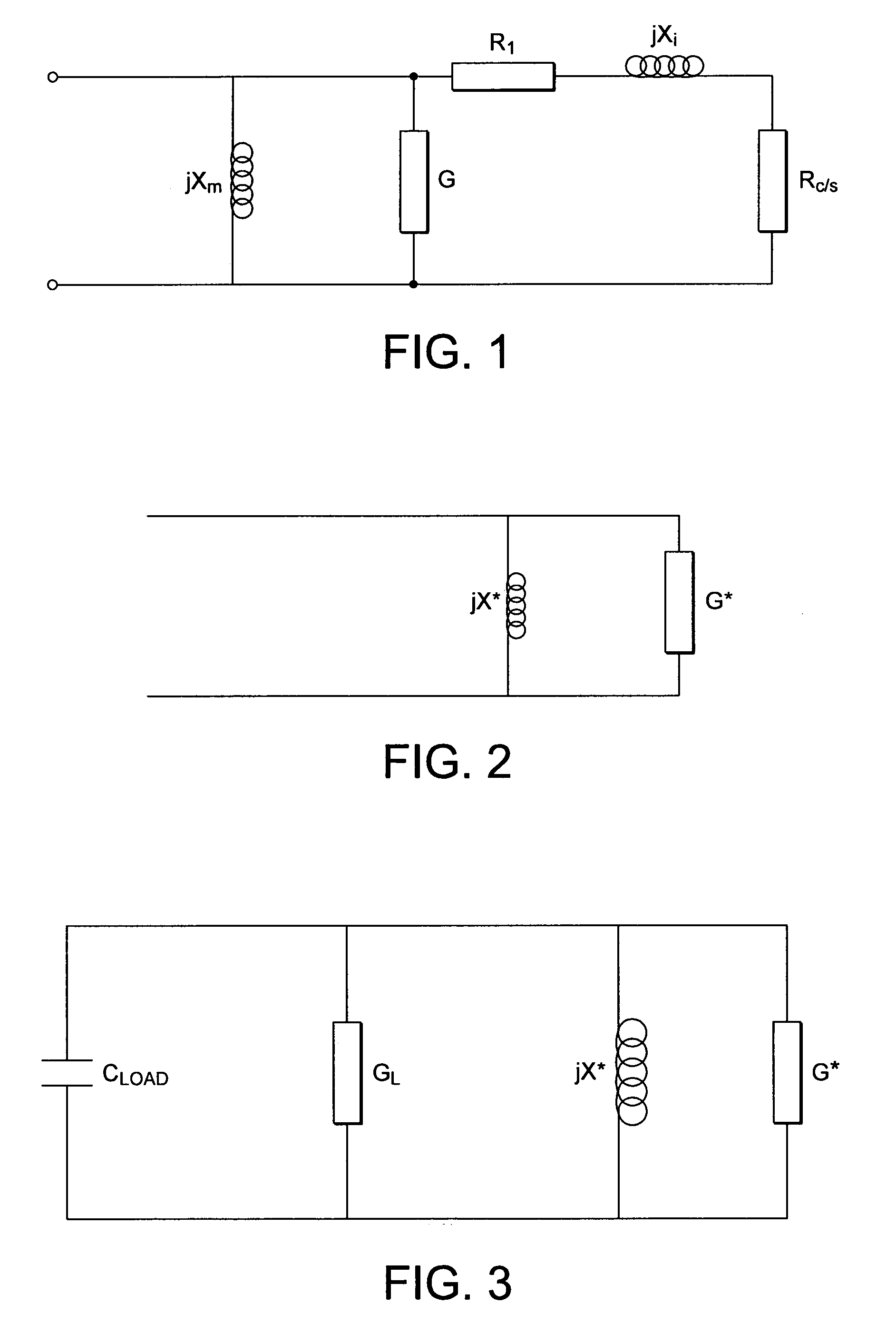
[0042]FIG. 1 shows an equivalent circuit for one of the phases of an induction generator. jXm is the impedance of the stator winding, G represents the iron losses, Rl represents the stator copper losses, jXl represents the imperfect coupling between the stator and rotor and Rc / s represents the squirrel-cage impedance where the value of the slip, s, is negative for generation and hence so is the value of the cage impedance. The values of Xl and Xm are, of course, frequency dependent.

[0043]At particular values of f...


PUM


Abstract

A wind turbine and generator arrangement comprises a turbine that drives a self-excited induction generator via a shaft and mechanical gearbox. The induction generator includes an electrical circuit that includes a variable capacitance and a variable resistance. The variable capacitance may be constituted by a fixed capacitor and a triac under the control of a controller, or by a bank of capacitors switched by a relay under control of the controller. The variable resistance includes a triac controlled resistor or a bank of relay-switched resistors which constitute heating elements for heating domestic hot water. In use the generator frequency and voltage are allowed to ‘float’ whilst the optimal generator power output is maintained, but adjusting the impedance of the electrical circuit as the wind speed varies.

Description

BACKGROUND OF THE INVENTION[0001]Asynchronous or induction generators have for some time formed the basis for the generation of electricity from wind turbines. They are attractive because of their relative simplicity, inexpensiveness and ruggedness. Various types of induction generators are known but all operate on the same basic principle: a prime mover (such as a turbine blade) delivers mechanical power to rotate a rotor, which rotates in the vicinity of the excited primary windings of a stator. In order to act as a generator, the rotor must be driven above (but only slightly above) its synchronous speed, that is, the rotor must rotate at a frequency which slightly exceeds the frequency of rotation of the magnetic field produced by the stator windings when energised (a so-called “negative slip” condition).[0002]Within the general category of induction generators, different specific constructions and methods of stator winding energisation are possible. One particular construction e...

Claims


Application Information

Patent Timeline
Patent Type & Authority Applications(United States)
IPC IPC(8): H05B3/78H02P9/04H05B3/00
CPCF03D7/0272F03D9/002F03D9/006H02P9/30H02P2101/15Y02B10/30Y02B10/70Y02E10/723Y02E10/725H02P9/46F03D9/22F03D9/25F03D15/10Y02E10/72
Inventor GREGG, JOHN FRANCISBARI, MAZHAR ALI
Owner OXFORD UNIV INNOVATION LTD
Why Eureka
Try Eureka