Charge air system and charge air operation method

a technology of charge air and operation method, which is applied in the direction of charge feed system, combustion engine, machine/engine, etc., can solve the problems of increased risk of condensation in one or more exhaust heat exchangers, especially in the second turbocharger stage, and the compressor wheel is more susceptible to damage, so as to reduce the risk of condensation and reduce the chemical emission value , the effect of eliminating condensation build-up

Active Publication Date: 2011-01-06
VOLVO LASTVAGNAR AB
View PDF26 Cites 38 Cited by
  • Summary
  • Abstract
  • Description
  • Claims
  • Application Information

AI Technical Summary

Benefits of technology

[0003]Modern vehicles are commonly employing exhaust gas recirculation in which exhaust gases are cooled and recirculated back into the combustion chamber to achieve lower chemical emission values. The U.S. Pat. No. 7,007,680 B2 discloses elimination of condensation build-up in the intake manifold and power cylinders by providing a bypass of a charge-air cooler (CAC) and / or an exhaust-gas-recirculation cooler (EGR) juxtaposed to the engine's intake manifold and thus controlling the intake manifold temperature to avoid condensation in the intake manifold. This prevents the formation of acids which could cause corrosion in the intake manifold and power cylinders when condensed water comes into contact with the recirculated exhaust gas.
[0004]It is desirable to provide a cooling system encompassing a dual stage turbocharger or mechanical compressor which has improved operationally reliability and durability it is also desirable to provide an operation method of the cooling system.
[0005]According to an aspect of the present invention, a charge air system for a combustion engine is proposed, comprising a first boosting system, e.g. a turbocharger stage, for compression of intake air supplied to the engine from a first pressure to a second pressure; a second turbocharger stage for compression of the compressed air to a third pressure; a first heat exchanger being arranged between the first and the second turbocharger stage for cooling the compressed air; a first intake air bypass for modulating the flow of the air, e.g. by at least partially bypassing or, preferably, by fully bypassing the first heat exchanger and / or a first mass flow control unit for controlling the flow of a cooling medium supplied to the first heat exchanger. Favourably, the temperature of the medium being discharged from the first heat exchanger can be kept well above the dew point temperature. Thus, condensation of water and a probable subsequent formation of ice particles can be avoided. As a high-pressure boost device, the second turbocharger stage is especially vulnerable to damage. Particularly during warm-up, low load, low ambient temperature damaging of the air compressor, particularly its compressor wheels, downstream of the first air heat exchanger by water droplets or ice particles breaking away from the first air heat exchanger can be prevented. This can be achieved by entire or partially (modulated) bypass of the air heat exchanger, one or more exhaust recirculation heat exchangers or cooling media and eventually combinations of modulating the amount of air in the bypass and the mass flow of the heat exchanger cooling medium.
[0006]In a favourable embodiment, a second heat exchanger can be provided downstream of the second turbocharger stage between the second turbocharger stage and an intake manifold of the engine. A second intake air bypass is provided for modulating the flow of the air through the second heat exchanger, e.g. by at least partially, preferably by fully bypassing the second heat exchanger. Additionally or alternatively, a second mass flow control unit can be provided for controlling the flow of a cooling medium supplied to the second heat exchanger. The first air heat exchanger is the low-pressure air cooler and the second heat exchanger is the high-pressure air cooler for the combustion oxidant, which can be ambient air or an air-exhaust mixture, if exhaust gas is recirculated to the intake manifold. Condensation of water downstream of the second turbocharger stage can be circumvented, preventing the engine intake manifold from damage such as corrosion. Downstream the second air heat exchanger, where the air is at the highest pressure, the risk of condensation of water is even higher than at the first heat exchanger stage as the temperature of the air or the air-exhaust mixture is roughly the same as behind the first air heat exchanger but the pressure is higher and therefore more probably condensation could occur. However, the compressor wheel is more vulnerable to damage as the intake manifold is for corrosion.

Problems solved by technology

As a high-pressure boost device, the second turbocharger stage is especially vulnerable to damage.
However, the compressor wheel is more vulnerable to damage as the intake manifold is for corrosion.
A risk for condensation is also present in the one or more exhaust heat exchangers, particularly if it is divided and cooled by air or a low temperature coolant circuit.
For a dual stage turbocharging water droplets and even ice particles can occur and damage the compressor wheel or other components of the boost element on the high pressure second turbocharger stage downstream of the first turbocharger stage.
For a single stage turbocharger this risk is also present but the consequences are minor compared to damaging a subsequent turbocharger stage.

Method used


Image

  • Charge air system and charge air operation method
  • Charge air system and charge air operation method
  • Charge air system and charge air operation method

Examples


Embodiment Construction

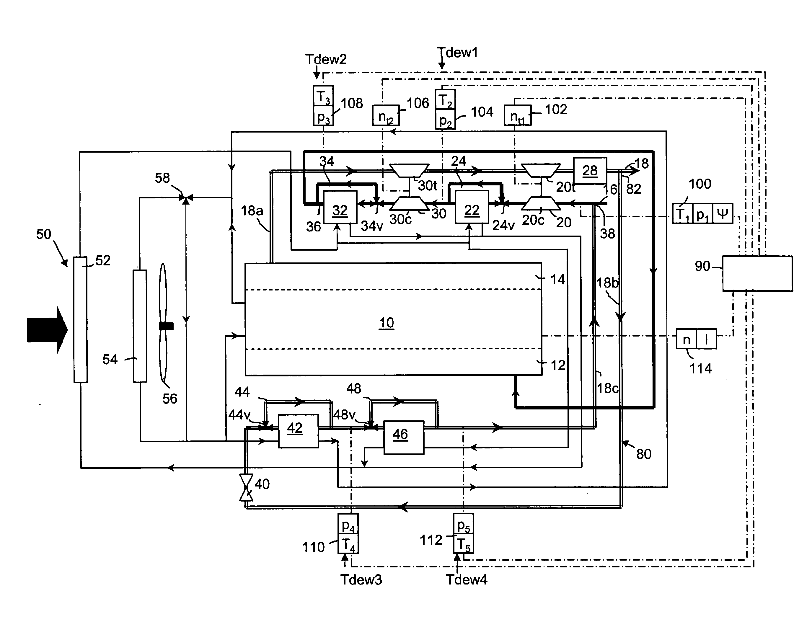
[0030]FIG. 1 depicts a first preferred embodiment of the invention. A cooling system for a combustion engine 10 of a vehicle comprises a first turbocharger stage 20 for compression of intake air supplied to the engine 10 from an ambient first pressure p1 to a second pressure p2, a second turbocharger stage 30 for compression of the compressed air to a third pressure p3, a first heat exchanger 22 being arranged between the first and the second turbocharger stage 20, 30 for cooling the compressed air, a first intake air bypass 24 for the air at least partially bypassing the first heat exchanger 22. the flow direction of the air is indicated by arrows in the air supply line 16.

[0031]The first turbocharger stage 20 encompasses a compressor 20c in the air supply line 16 and a turbine 2Ot in the exhaust line 18. The second turbocharger stage 30 encompasses a compressor 30c in the air supply line 16 and a turbine 3Ot in the exhaust line 18. The turbines 2Ot, 3Ot drive the compressor wheels...


PUM


Abstract

A charge air system for a combustion engine and an operation method are provided. The charge air system includes a first turbocharger stage for intake of combustion air supplied to the engine from a first pressure to a second pressure, a second turbocharger stage for compression of the compressed air to a third pressure, a first heat exchanger being arranged between the first and the second turbocharger stage for cooling the compressed air, a first intake air bypass for modulating the flow of the air through the first heat exchanger and/or a first mass flow control unit for controlling the flow of a cooling medium supplied to the first heat exchanger.

Description

BACKGROUND AND SUMMARY[0001]The invention relates to a charge air and a charge air operation method.[0002]During engine operation water can condense in the charge air system and the inlet manifold and power cylinders of an engine when the intake air temperature drops below the dew-point temperature. The dew point temperature can be defined as a temperature at which a gas would reach saturation for a given boost pressure and ambient humidity conditions.[0003]Modern vehicles are commonly employing exhaust gas recirculation in which exhaust gases are cooled and recirculated back into the combustion chamber to achieve lower chemical emission values. The U.S. Pat. No. 7,007,680 B2 discloses elimination of condensation build-up in the intake manifold and power cylinders by providing a bypass of a charge-air cooler (CAC) and / or an exhaust-gas-recirculation cooler (EGR) juxtaposed to the engine's intake manifold and thus controlling the intake manifold temperature to avoid condensation in t...

Claims


Application Information

Patent Timeline
Patent Type & Authority Applications(United States)
IPC IPC(8): F02B33/00F02M15/00
CPCF02B29/0412F02B29/0418F02B29/0468F02B37/004F02B37/013Y02T10/146Y02T10/144F02B29/0493Y02T10/12
Inventor LAUBERTS, PETERISBERTILSSON, BERT-INGE
Owner VOLVO LASTVAGNAR AB
Why Eureka
Try Eureka