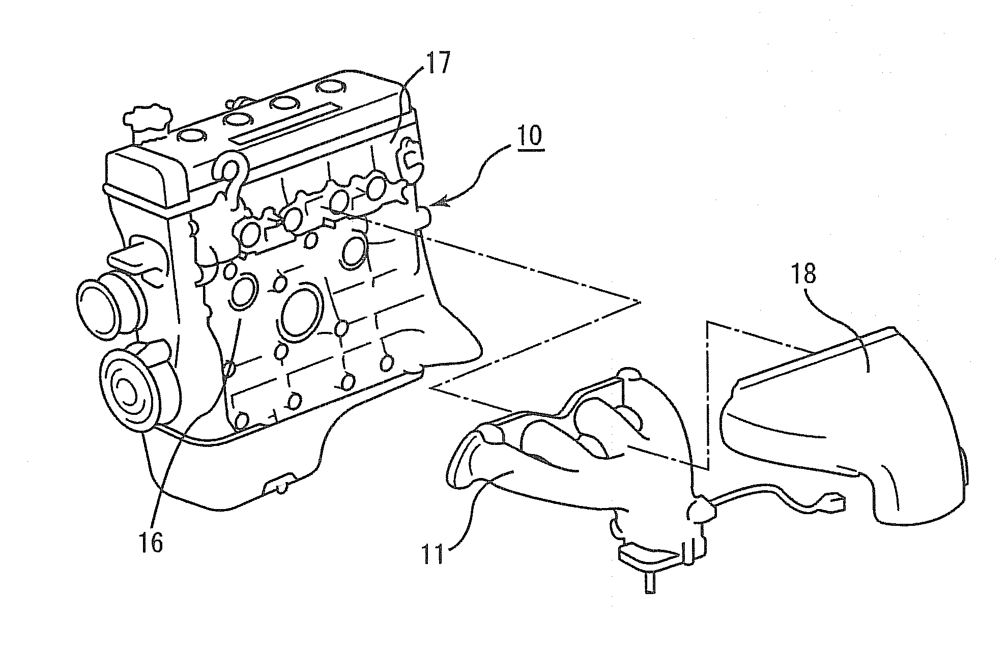
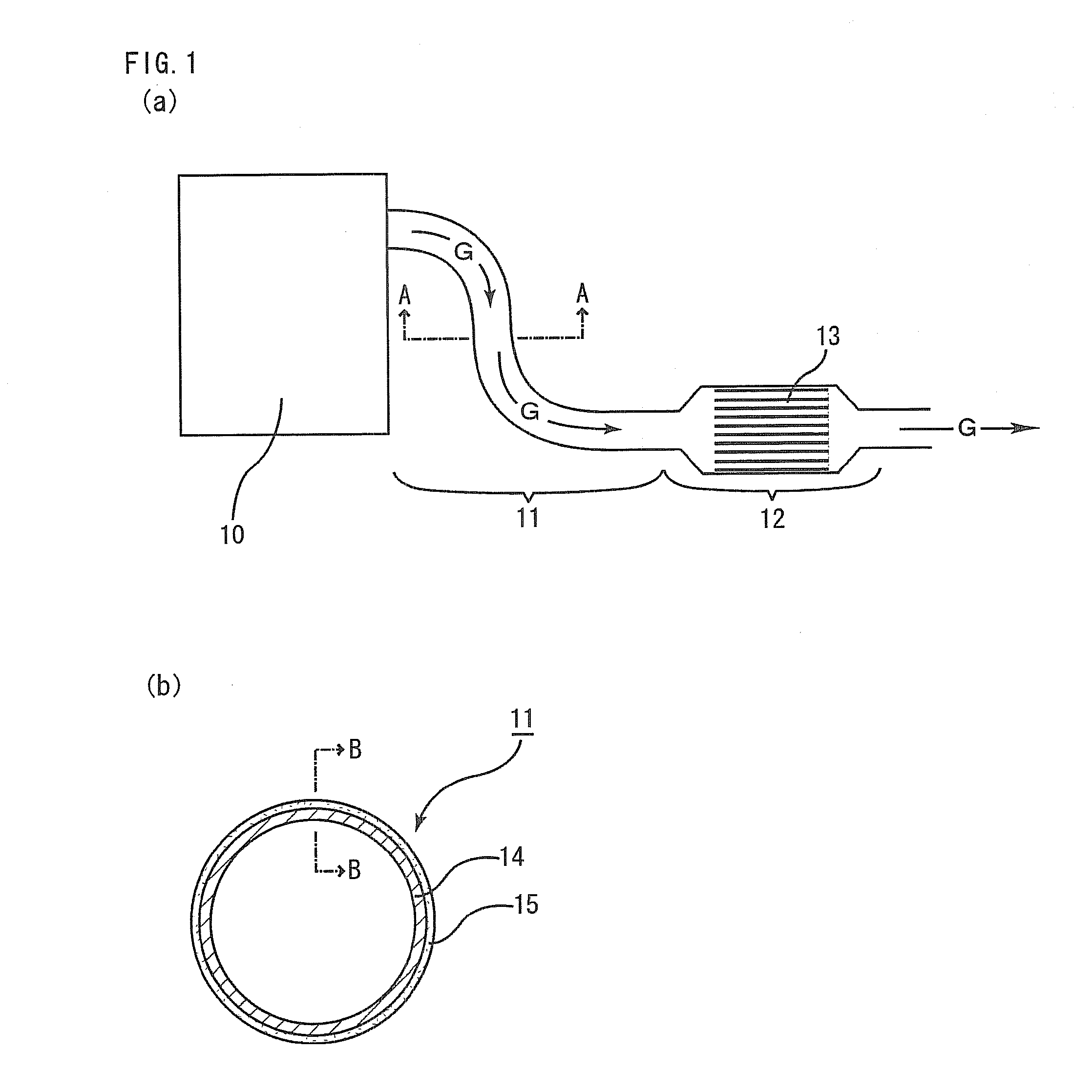
Exhaust pipe

a technology of exhaust pipe and exhaust gas, which is applied in the direction of machines/engines, mechanical equipment, surface coverings, etc., can solve the problems of increased discharge amount of contaminants, lowered fuel efficiency, and increased exhaust gas discharge, so as to facilitate heat transfer

Active Publication Date: 2011-01-06
IBIDEN CO LTD +1
View PDF9 Cites 20 Cited by
  • Summary
  • Abstract
  • Description
  • Claims
  • Application Information

AI Technical Summary

Benefits of technology

[0022]According to the exhaust pipe described in claim 2, provision of the heat-receiving member facilitates heat transfer from the exhaust pipe body to the heat-receiving member, and thereby heat release from the exhaust pipe body more surely proceeds.

Problems solved by technology

In such a case, however, a problem is occurred that fuel efficiency is lowered and concentration of exhaust gases is raised, so that a discharge amount of contaminants is increased.
Further, when the temperature of the exhaust pipe is raised by a flow of exhaust gases, it causes heat degradation of the exhaust pipe.
However, in a high-speed operation of a vehicle engine, exhaust gases become very hot and there may be a case where the temperature of a three-way catalyst becomes out of the effective range for conversion of exhaust gases and fails to convert contaminants properly.
Moreover, there may be a case where the three-way catalyst is thermally deteriorated due to high-temperature exhaust gases.

Method used


Image

  • Exhaust pipe
  • Exhaust pipe
  • Exhaust pipe

Examples


example 1

[0155](1) A cylindrical (cross sectional shape is substantially perfect circle) metal base having a diameter (external diameter) of 40 mm, a thickness of 2 mm, and a length of 300 mm was used as a starting material. The metal base was made of SUS430 and had the following properties: thermal conductivity at 100 to 200° C.: 25 W / mK; emissivity at a wavelength of 1 to 15 μm at 600° C.: 0.30; and coefficient of thermal expansion in a temperature range of room temperature to 500° C.: 10.4×10⁻⁶ / ° C. First, this metal base was ultrasonically cleaned in an alcohol solvent, and then sandblasted to make the outer peripheral face of the metal base into a rough face having the maximum height Rz of 2.5 μm. The sandblasting was performed for 10 minutes using Al2O3 abrasive grains of #80.

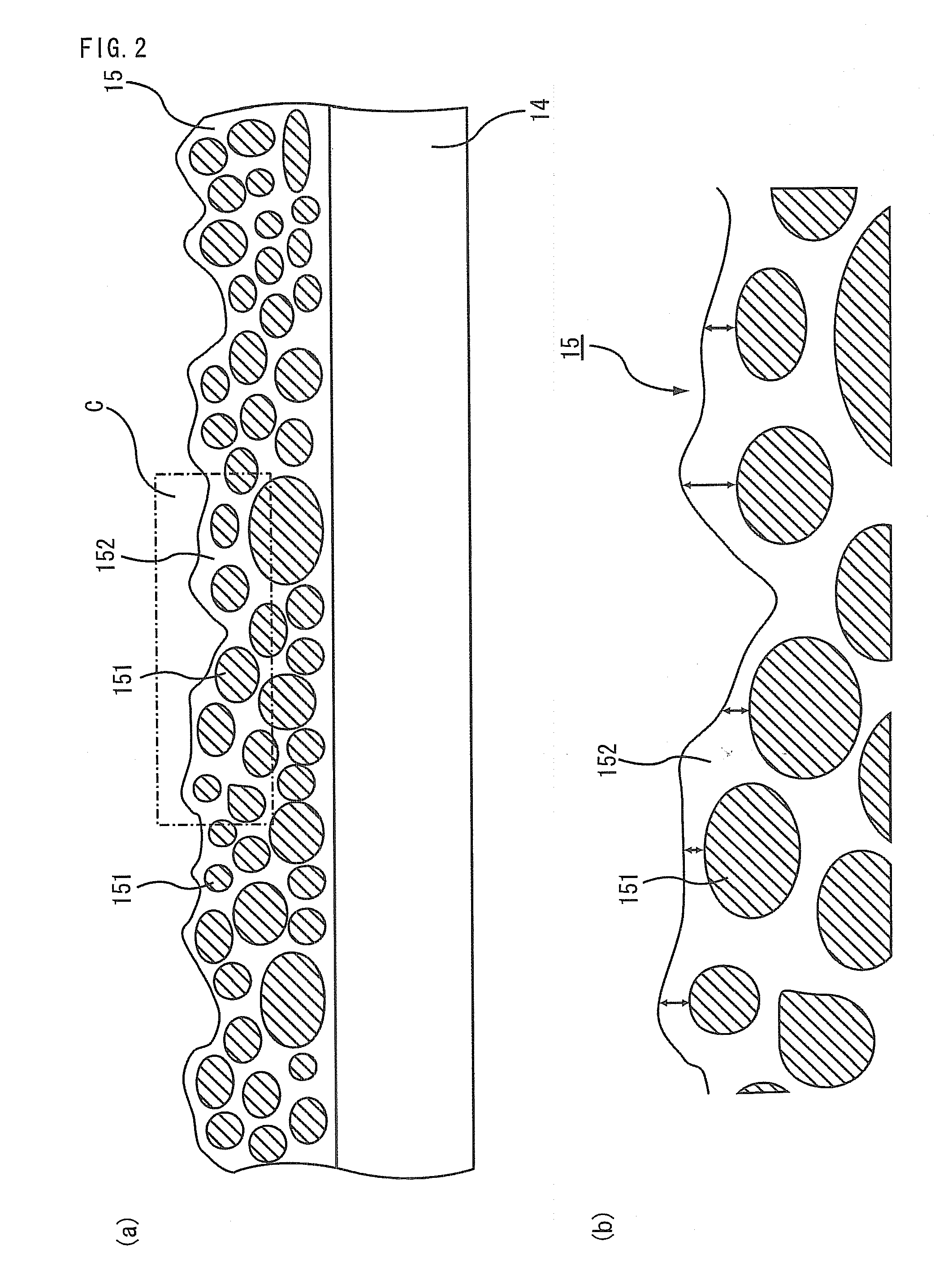
[0156](2) Separately, 30% by weight of a MnO2 powder, 5% by weight of a FeO powder and 5% by weight of a CuO powder as crystalline inorganic materials, and 60% by weight of a BaO—SiO2 glass powder as an amorphous ...

examples 2 to 5

[0165]Each exhaust pipe body was produced in the same way as in Example 1 except that the average thickness of the amorphous binder at a location nearer the outer peripheral face of the exhaust pipe body than a location of crystalline inorganic materials was set to the thickness shown in Table 1.

[0166]The average thickness was adjusted by controlling the firing temperature.

[0167]That is, the firing temperature was changed to 850° C. in Example 2, 820° C. in Example 3, 800° C. in Example 4, and 780° C. in Example 5.


PUM

PropertyMeasurementUnit
thicknessaaaaaaaaaa
emissivityaaaaaaaaaa
softening temperatureaaaaaaaaaa

Abstract

An exhaust pipe devised to, at the flow of high-temperature exhaust gas through the exhaust pipe, lower the temperature of the exhaust gas. The exhaust pipe has the following characteristics. The exhaust pipe has a tubular base material of metal and, provided on the outer circumferential surface of the base material, a surface coating layer composed of a crystalline inorganic material and an amorphous binder material. In the surface coating layer, the crystalline inorganic material is distributed in the state of being multiply stacked one upon another in the direction of thickness of the surface coating layer. The average thickness of the amorphous binder material located on the side of outer circumferential surface relative to the crystalline inorganic material is 20 μm or less. The exhaust gas flows through the interior of the pipe.

Description

TECHNICAL FIELD[0001]The present invention relates to an exhaust pipe.BACKGROUND ART[0002]An exhaust pipe connected to a vehicle engine becomes significantly hot in driving operation because combustion gases (exhaust gases) flow inside thereof. In a high-load and high-revolution area of the engine, fuel is increased so as to avoid a rise in temperature of exhaust gases. In such a case, however, a problem is occurred that fuel efficiency is lowered and concentration of exhaust gases is raised, so that a discharge amount of contaminants is increased.[0003]Further, when the temperature of the exhaust pipe is raised by a flow of exhaust gases, it causes heat degradation of the exhaust pipe.[0004]Inside an exhaust pipe, a catalyst is provided for converting exhaust gases discharged from a vehicle engine. For example, a three-way catalyst can convert contaminants such as nitrogen carbide (HC), carbon monoxide (CO), and nitrogen oxide (NOx) which are contained in exhaust gases.[0005]In ord...

Claims


Application Information

Patent Timeline
Patent Type & Authority Applications(United States)
IPC IPC(8): F16L9/00F01N13/16C23C26/00C23C30/00F01N13/08
CPCC23C24/00C23C26/00F01N13/08F01N13/082F01N13/141F01N2530/26F01N2260/02F01N2260/08F01N2260/20F01N2510/02F01N13/16
Inventor ITO, YASUTAKAWAKAMATSU, JIN
Owner IBIDEN CO LTD
Why Eureka
Try Eureka