Forming uniform silicide on 3D structures

a three-dimensional structure and uniform technology, applied in the field of silicide formation on three-dimensional structures, can solve the problem of not much coverage on the sidewall, and achieve the effect of thickness and coverage control

Inactive Publication Date: 2011-01-06
GLOBALFOUNDRIES INC
View PDF14 Cites 39 Cited by
  • Summary
  • Abstract
  • Description
  • Claims
  • Application Information

AI Technical Summary

Benefits of technology

[0059]Therefore, if you want to silicide a fin and use sputtering, for example, to deposit the metal (siliciding material), the result will be a large amount of silicide on the top (horizontal surface) of the fin and; much less silicide on vertical side(s) of the fin. In the contact geometry suggested in FIG. 2A, most of the contact area is along the sides of the fin (the top of the fin is very narrow). As a result, such a silicidation process leads to higher contact resistance since the lower part of the Fin is typically not silicided significantly.
[0063]An ultrathin thin diffusion barrier, to partially prevent Ni from penetrating the Si, is first deposited on the Fin. This film is not a full barrier, it only retards diffusion of Ni in proportion to its thickness. The film is deposited using similar non conformal techniques as for the subsequent Ni film deposition and its morphology will thus be similar. It is preferentially deposited thinner on vertical sidewalls of the fin and will thus allow more Ni diffusion at the sidewalls (vertical surface) than on the top of the structure (horizontal surface) where the diffusion barrier is thicker. Titanium (Ti) and Titanium Nitride (TiN) are well known diffusion barriers that can partially filter (inhibit) Ni diffusion when the films are extremely thin (˜2 nm or thinner).
[0064]Thickness and coverage control for Ti or TiN can be easily achieved by adjusting deposition conditions. The desired barrier profile is intrinsically possible by sputter deposition. The advantage of this scheme is to form a controlled uniform thickness silicide over the fin surface.

Problems solved by technology

Deposition tools commonly used for metal deposition, such as by sputtering (or evaporation), are generally non-conformal, and result in much less metal deposited on the sides of a structure (such as a fin) than on the top.
This may be beneficial for filling narrow canyons (trenches), but results in not much coverage on sidewalls.

Method used


Image

  • Forming uniform silicide on 3D structures
  • Forming uniform silicide on 3D structures
  • Forming uniform silicide on 3D structures

Examples


Embodiment Construction

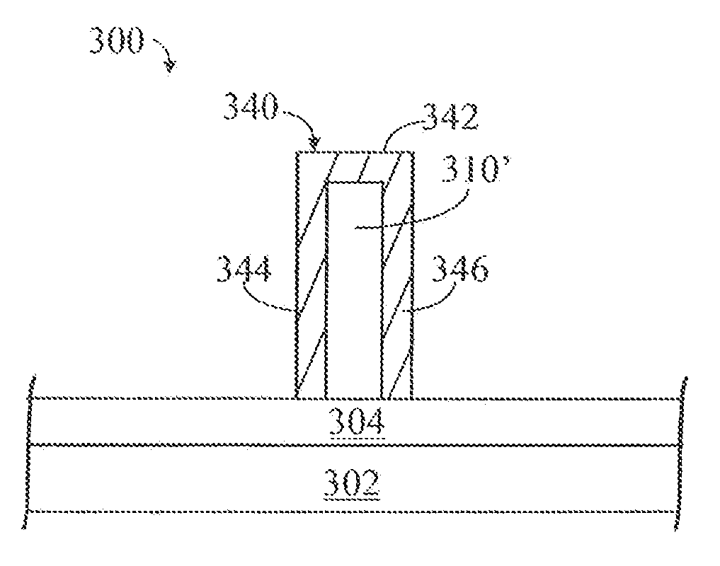
[0083]In the description that follows, numerous details are set forth in order to provide a thorough understanding of the present invention. It will be appreciated by those skilled in the art that variations of these specific details are possible while still achieving the results of the present invention. Well-known processing steps and materials are generally not described in detail in order to avoid unnecessarily complicating the description of the present invention.

[0084]Materials (e.g., silicon dioxide) may be referred to by their formal and / or common names, as well as by their chemical formula. Regarding chemical formulas, numbers may be presented in normal font rather than as subscripts. For example, silicon dioxide may be referred to simply as “oxide”, chemical formula SiO2. For example, silicon nitride (stoichiometric Si3N4, often abbreviated as “SiN”) may be referred to simply as “nitride”.

[0085]In the description that follows, exemplary dimensions may be presented for an i...


PUM

PropertyMeasurementUnit
thicknessaaaaaaaaaa
thicknessaaaaaaaaaa
thicknessaaaaaaaaaa

Abstract

By using a non-conformal diffusion barrier in conjunction with a similarly deposited non-conformal initial deposition of siliciding material, a substantially uniform and conformal silicide can be formed in a 3D structure such as the fin of a FinFET. The siliciding material may be nickel (Ni), the diffusion barrier may be titanium (Ti) or titanium nitride (TiN). Generally, the diffusion barrier may be any material which will inhibit, but not block, diffusion of the siliciding material into the silicon. In this manner, a non-conformal barrier deposition, in conjunction with a non-conformal silicide material deposition, after anneal, results in substantially conformal silicide formation.

Description

BACKGROUND[0001]The present invention generally relates to semiconductor device fabrication and, more particularly, to siliciding three-dimensional (3D) structures such as FinFETs.[0002]The fabrication of microelectronic semiconductor devices, commonly referred to as integrated circuits (ICs) may generally involve the processes of depositing materials on and removing materials from a semiconductor substrate such as a silicon wafer. Other processes such as diffusion, annealing may also be involved. Some of these materials and processes may be described herein. Generally, the individual processes which are involved are well known.[0003]The semiconductor substrate, typically in the form of a wafer, may be a semiconductor material such as silicon, germanium, silicon germanium, silicon carbide, and those consisting essentially of III-V compound semiconductors such as GaAs, II-VI compound semiconductors such as ZnSe. Silicon on insulator (SOI) technology refers to the use of a layered sil...

Claims


Application Information

Patent Timeline
Patent Type & Authority Applications(United States)
IPC IPC(8): H01L29/49H01L21/3205
CPCH01L21/28518H01L29/41791H01L2029/7858H01L29/785H01L29/66795
Inventor OZCAN, AHMET S.LAVOIE, CHRISTIAN
Owner GLOBALFOUNDRIES INC
Why Eureka
Try Eureka