Eureka AIR delivers breakthrough ideas for toughest innovation challenges, trusted by R&D personnel around the world.

Microchannel with internal fin support for catalyst or sorption medium

a microchannel and catalyst technology, applied in the field of microchannels, can solve the problems of insufficient surface area for many processes, difficult to provide adequate catalytic surface area for the process to operate effectively, and difficult to provide sufficient mass transport distances. achieve the effect of enhancing heat transfer, fast thermal swing, and fast cycle tim

Inactive Publication Date: 2011-01-06
VELOCYS CORPORATION
View PDF100 Cites 15 Cited by
  • Summary
  • Abstract
  • Description
  • Claims
  • Application Information

AI Technical Summary

Benefits of technology

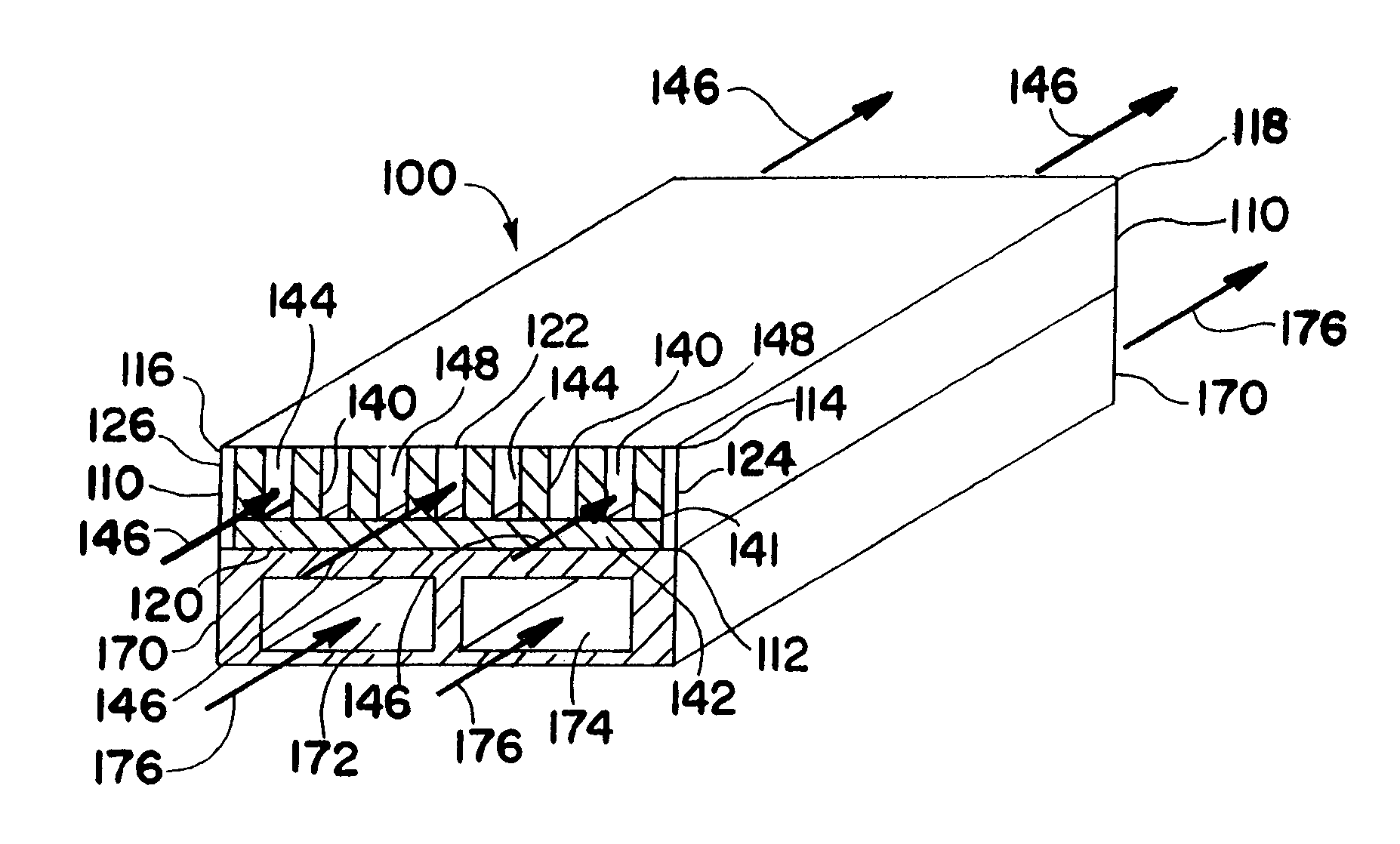
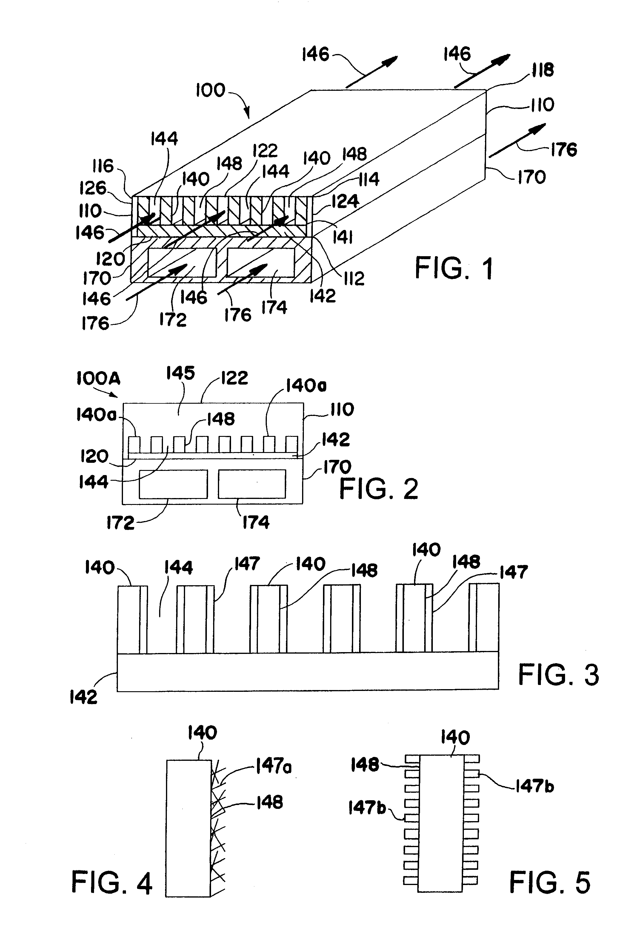
[0083]An advantage of the invention is that the use of a fin structure to support an active sorption medium enables a relatively fast thermal swing. A metallic fin structure may have a thermal conductivity in the range of about 10 to about 20 W / m / K or greater depending on the material selected. Aluminum may exceed 100 W / m / K. On the other hand, the thermal conductivity of a porous medium such as a pellet or powder sorbent bed is typically in the range of about 0.2 to about 2 W / m / K. As a result, the use of a fin supported sorption medium enables faster cycle times due to enhanced heat transfer through the fin versus a porous medium. The difference in cycle time is roughly proportional to the difference in thermal conductivity of the sorption medium. The use of a fin supported sorption medium permits the time for each cycle to be reduced significantly as compared to a porous sorption medium. This enhancement in cycle times facilitates both gas phase and liquid phase sorption separation processes.
is that the use of a fin structure to support an active sorption medium enables a relatively fast thermal swing. A metallic fin structure may have a thermal conductivity in the range of about 10 to about 20 W / m / K or greater depending on the material selected. Aluminum may exceed 100 W / m / K. On the other hand, the thermal conductivity of a porous medium such as a pellet or powder sorbent bed is typically in the range of about 0.2 to about 2 W / m / K. As a result, the use of a fin supported sorption medium enables faster cycle times due to enhanced heat transfer through the fin versus a porous medium. The difference in cycle time is roughly proportional to the difference in thermal conductivity of the sorption medium. The use of a fin supported sorption medium permits the time for each cycle to be reduced significantly as compared to a porous sorption medium. This enhancement in cycle times facilitates both gas phase and liquid phase sorption separation processes.

Problems solved by technology

A problem with these microchannel reactors relates to the fact that for many processes it is difficult to provide adequate catalytic surface area for the process to operate effectively.
Also, for many processes it is difficult to provide sufficiently short mass transport distances for the reactants to the catalytic surface area for the process to operate effectively.
A problem with the use of these washcoats is that the additional surface area that is provided is not sufficient for many processes.
A problem with each of these support structures is that the thermal conductivity provided by these support structures is inadequate for many processes.
A problem with microchannel reactors that are coupled with adjacent heat exchangers relates to the relatively high pressure drop that often occurs as a result of the small internal dimensions of the microchannels when high heat flux or high throughput is desired.
If the microchannel height or width is maintained relatively small to overcome mass transport limitations, the pressure drop tends to increase in inverse proportion to the channel height or width, potentially limiting maximum throughput.

Method used


Image

  • Microchannel with internal fin support for catalyst or sorption medium
  • Microchannel with internal fin support for catalyst or sorption medium
  • Microchannel with internal fin support for catalyst or sorption medium

Examples


example 1

[0084]A steam / methane reforming (SMR) process with integrated combustion on the opposing side of the heat transfer plane is conducted in a microchannel reactor employing an FeCrAlY fin supported SMR catalyst. The use of an SMR catalyst on fins inserted in a process microchannel produces surprisingly high heat fluxes (10 to 141 W / cm2, low SMR contact times (10 to 0.7 ms), and low SMR pressure drops.

[0085]Except for the FeCrAlY fin which supports the SMR catalyst, the microchannel reactor is constructed of Inconel 617 plates of various thicknesses which are stacked, clamped together, and welded at the perimeter to form a reactor 0.5 by 3.63 inch (12.7 by 92 mm) in footprint by 0.67 inch (17.1 mm) high. All channels for gas flow are machined using conventional techniques except air jet orifices, which are formed via electrode discharge machining (EDM). An air header plate (6.35 mm thick with a 12.7 by 56.5 mm footprint) is welded in a 2.54 mm deep pocket machined into a combustion plat...

example 2

[0101]Fins for use in a partial oxidation reaction process are designed and tested for methane partial oxidation to synthesis gas with focus on following characteristics:[0102]1. High CH4 conversion: use of the fin should provide high CH4 conversion.[0103]2. High H2 Selectivity: use of the fin should provide high H2 selectivity.[0104]3. High CO Selectivity: use of the fin should provide high CO selectivity.[0105]4. Low Pressure Drop: use of the fin should offer low resistance to flow.[0106]5. Mechanical and thermal strength: The fin should have high mechanical strength to sustain large stress conditions inside the channel during fabrication of the device (like bonding) and its operation. A design with good heat transfer characteristics prevents hot spots and material degradation.

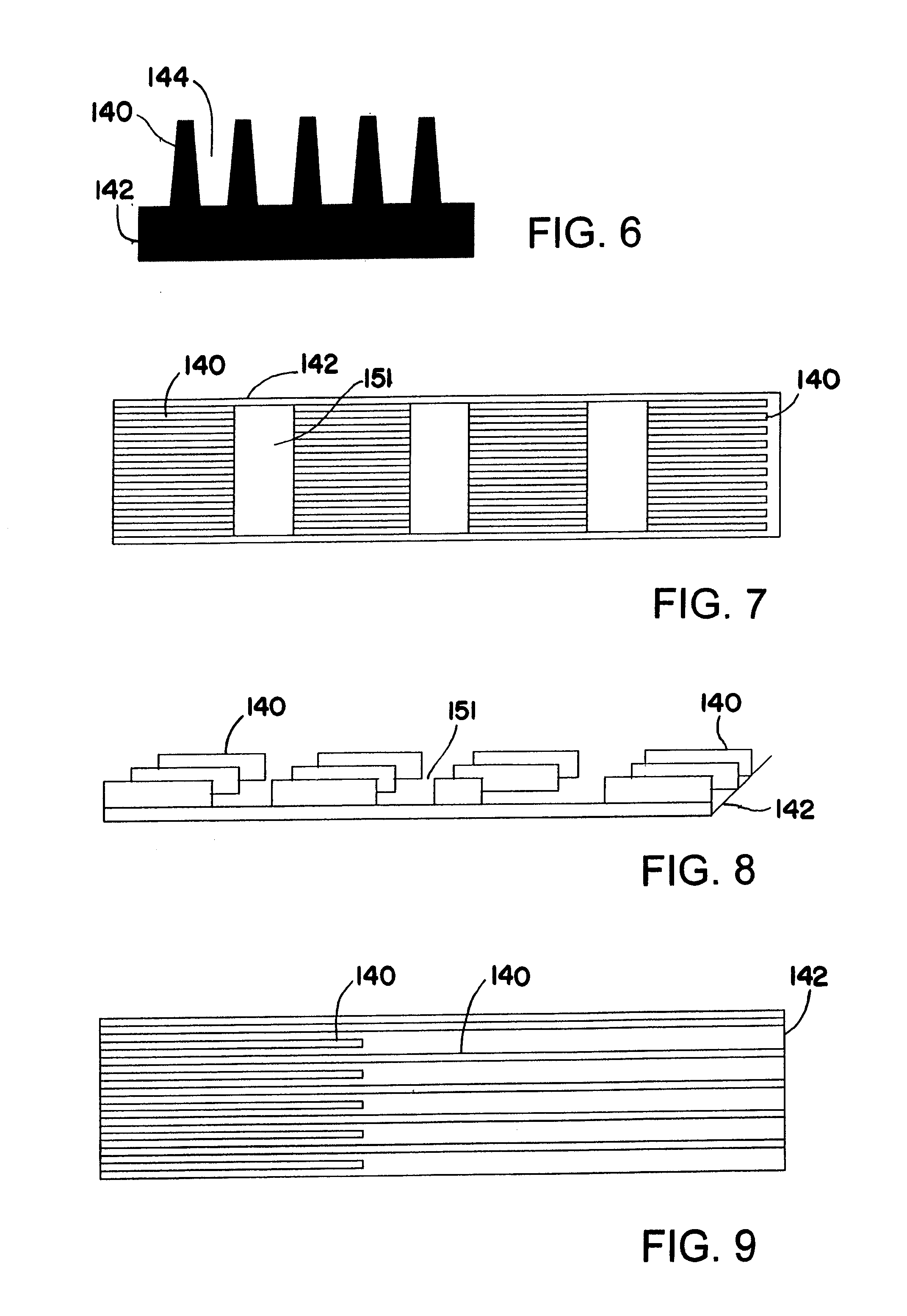
[0107]FIG. 6 shows the geometry of a fin that is useful for conducting a PDX reaction process in a combustion microchannel. The trapezoidal shape of the fins provides mechanical rigidity at the base of fins....

example 3

[0110]An alternate fin for use in a PDX reaction process provides the advantage of reduced pressure drop. The flow area is increased by reducing number of fins. There are five fins projecting up from the fin support. The fins have a trapezoidal cross section as indicated in FIG. 6. The thickness of the fin along with trapezoidal shape of the fins provides mechanical rigidity at the base of the fins. The fins are supported on rectangular support or base to enhance heat transfer characteristics of the fin. The fin is made from FeCrAlY. The fin is fabricated by the wire EDM methnd The following table summarizes dimensions of the fin:

Dimension (in)Fin ThicknessAt base0.020″At top0.010″Fin spacingAt base0.012″At top0.022″Fin height0.033″Rectangular base height0.020″Overall width0.180″Overall height0.053″Overall length1.500″

[0111]An Al2O3 slurry is prepared by mixing 7.2 g of gamma Al2O3 powder, 12 g of deionized H2O and 42 g Al2O3 beads with 3 mm diameter. The pH value is adjusted to 3.5...


PUM

PropertyMeasurementUnit
pore sizeaaaaaaaaaa
heightaaaaaaaaaa
heightaaaaaaaaaa

Abstract

This invention relates to an apparatus, comprising: at least one process microchannel having a height, width and length, the height being up to about 10 mm, the process microchannel having a base wall extending in one direction along the width of the process microchannel and in another direction along the length of the process microchannel; at least one fin projecting into the process microchannel from the base wall and extending along at least part of the length of the process microchannel; and a catalyst or sorption medium supported by the fin.

Description

CROSS-REFERENCE TO RELATED APPLICATIONS [0001]This application is a continuation application of U.S. application Ser. No. 11 / 617,518, filed Dec. 28, 2006, which is a continuation application of U.S. application Ser. No. 10 / 440,053, filed May 16, 2003 (now U.S. Pat. No. 7,220,390 B2), these applications being incorporated herein by reference.TECHNICAL FIELD [0002]This invention relates to microchannels containing an internal fin for supporting a catalyst or sorption medium. These microchannels are suitable for use in conducting catalytically activated chemical reactions and separating fluids using sorption mediums.BACKGROUND OF THE INVENTION[0003]Microchannel reactors may be used in a variety of catalytic processes wherein reactants contact a catalyst within the microchannel reactor and undergo reaction. The term “microchannel” is used herein to refer to a channel having an internal width or height up to about 10 mm. A problem with these microchannel reactors relates to the fact that...

Claims


Application Information

Patent Timeline
Patent Type & Authority Applications(United States)
IPC IPC(8): B01J8/02B01D53/02
CPCB01D53/0438Y02C20/20B01D2256/245B01D2257/102B01D2257/7025B01D2259/40092B01J19/0093B01J2219/00783B01J2219/00822B01J2219/00824B01J2219/00831B01J2219/00833B01J2219/00835B01J2219/00855B01J2219/0086B01J2219/00873B01J2219/00889G06F8/38B01D53/0462
Inventor TONKOVICH, ANNA LEEQIU, DONGMINGLONG, RICHARD Q.YANG, BARRY L.YUSCHAK, THOMASPERRY, STEVEN T.
Owner VELOCYS CORPORATION
Why Eureka
Eureka Blog
Learn More