Atherectomy catheter with laterally-displaceable tip

a catheter and lateral technology, applied in the field of catheters with laterally displaceable tips, can solve the problems of limited market adoption, need for large access devices, and traditional atherectomy devices, and achieve the effects of minimizing the depth of cut, reducing procedure time, and maximizing the cross-sectional area of cut tissu

Active Publication Date: 2011-01-06
AVINGER
View PDF108 Cites 150 Cited by
  • Summary
  • Abstract
  • Description
  • Claims
  • Application Information

AI Technical Summary

Benefits of technology

[0024]Atherectomy catheters and systems using them may have a cutter (e.g., the cutting edge of an annular cutting ring) diameter at or near the maximum crossing profile of the main catheter body, which may maximize cut tissue cross-sectional area, and minimize the depth of cut. The large cross-sectional area may reduce the procedure time, providing more efficient cutting passes and add a degree of safety by reducing the depth of cut required to achieve these efficiencies. The depth of the cut may be controlled by the lateral displacement of the distal end of the device, which both determines the opening size and how much of the cutter is exposed, and may also drive the cutter against the wall of the vessel by effectively widening the device within the vessel lumen.
[0025]The hollow cutters (annular cutting rings) described may allow tissue to be cut from the wall of the artery, pass directly through the catheter, and be stored in a reservoir. Both forward-cutting (push-cutting devices) and reverse (pull) cutting devices are described. In pull-cutting devices, the tissue may preferentially be stored distally, which in push cutting devices, the tissue may be preferentially be stored proximally. In some variations a deflector or guide may be used to direct the cut tissue into a proximal and/or distal storage area within the device. Proximal tissue storage may allow the distal tip region diameters and lengths to be reduced. Reduced tip dimensions may help the device cross tight lesions, cut in quickly tapering vessels, and generally be less traumatic to downstream vasc

Problems solved by technology

Traditional atherectomy devices have been plagued by a number of problems, which have severely limited market adoption.
These challenges include the need for large access devices, rigid distal assemblies that make control and introduction challenging, fixed cut length, unpredictable depth of cut, insufficient tissue collection and removal, and complex operation.
Despite the potential to improve restenosis rates associated with angioplasty and stenting in the coronary and peripheral vasculature, atherectomy is not commonly performed.
The primary reason for this limited use is the cost, complexity and limited applicability of currently available devices.
Many designs are unable to treat the wide range of disease states present in long complex lesions; luminal gain is often limited by the requirement of the physician to introduce multiple devices with increased crossing profiles; tissue collection is either unpredictable or considered unnecessary based on assumptions regarding small particle size and volumes; and optimal debulking is either not possible

Method used


Image

  • Atherectomy catheter with laterally-displaceable tip
  • Atherectomy catheter with laterally-displaceable tip
  • Atherectomy catheter with laterally-displaceable tip

Examples


Embodiment Construction

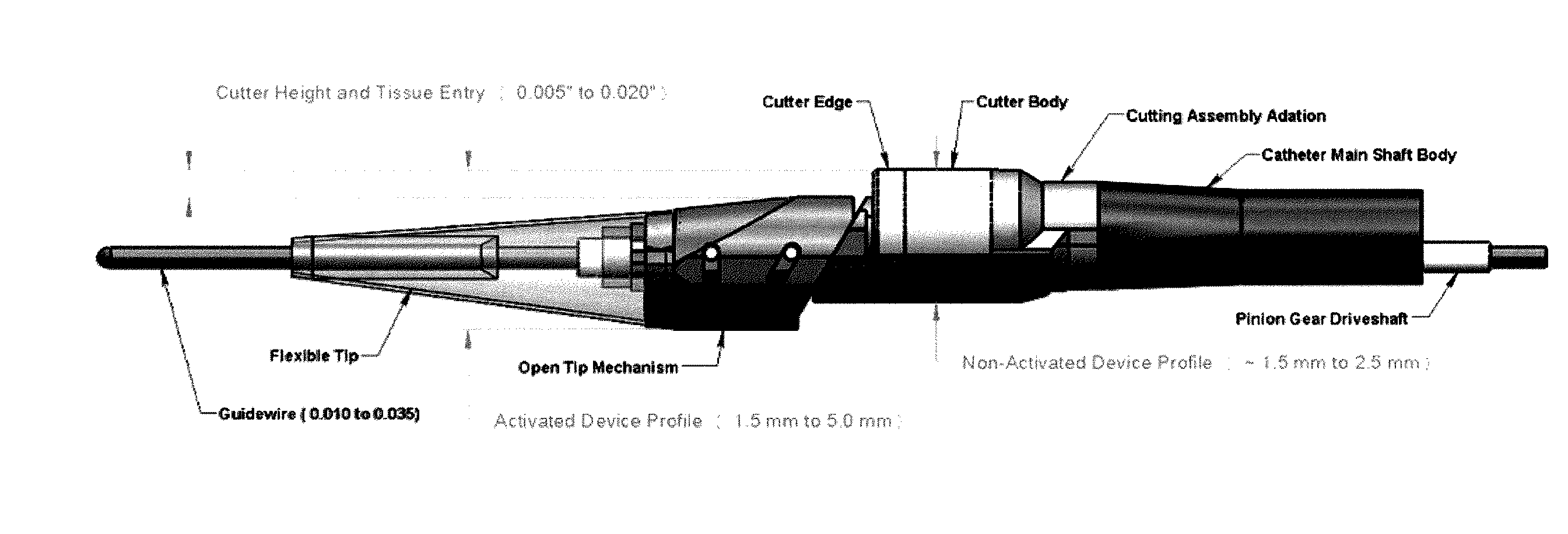
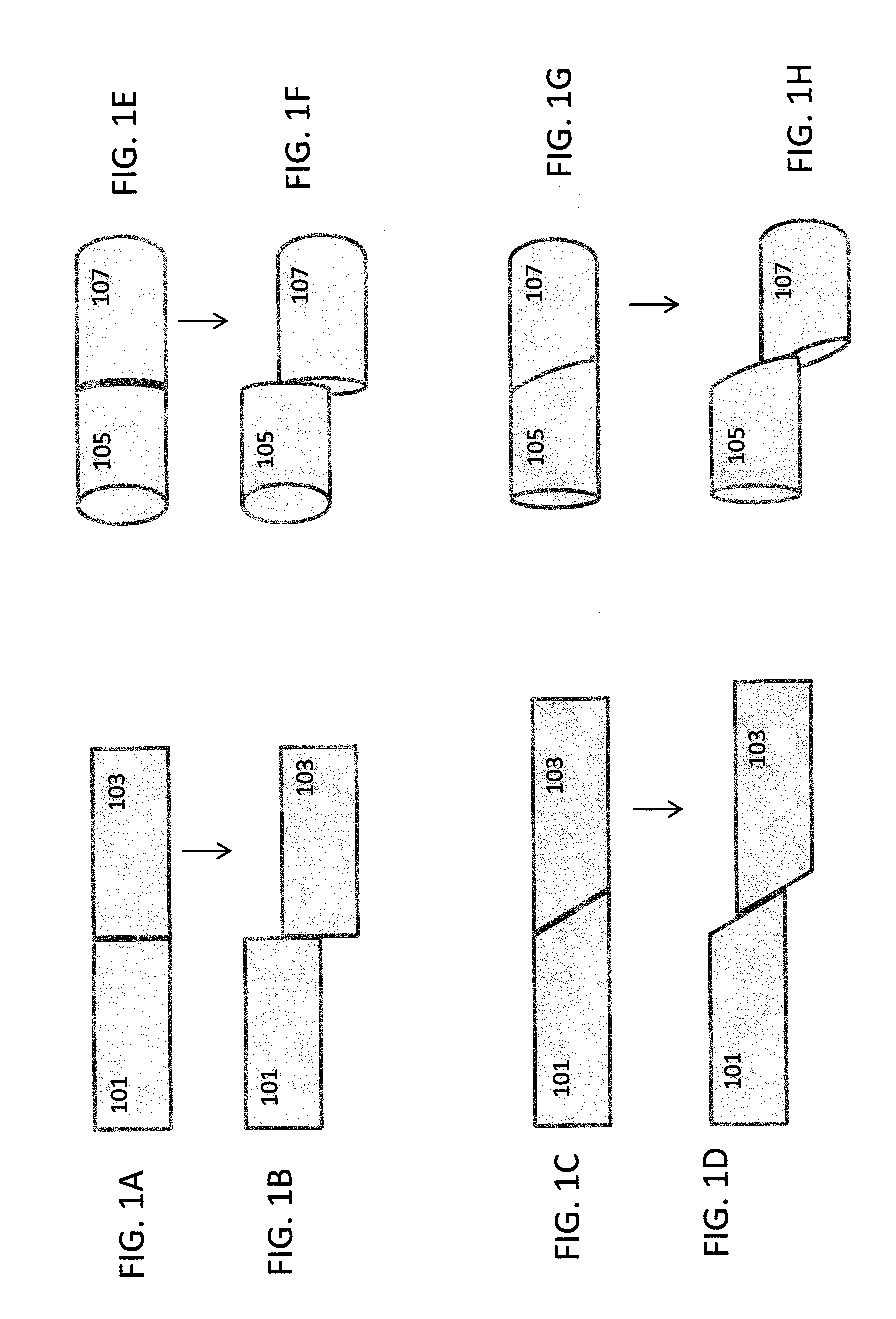
[0075]In general the atherectomy devices described herein include laterally displaceable distal tip regions. FIG. 1A-1H illustrate examples of lateral displacement. As used herein, lateral displacement includes movement of the distal tip region of a catheter from a first position in which the long axis of the distal tip region (the longitudinal axis of the distal tip region) is in-line with the long axis of the proximal body of the catheter (the longitudinal axis of the catheter body) to a second, laterally displaced, position in which the distal tip region has shifted out plane so that the long axis of the distal tip region is parallel with the long axis of the catheter body, but in a different plane. The terms “parallel” and “in line” in reference to the long or longitudinal axis do not require that the catheter regions be straight.

[0076]FIGS. 1A and 1B, illustrate lateral displacement of a rectangular region having a proximal 101 and distal 103 elements. In FIG. 1A, the proximal ...


PUM


Abstract

Described herein are atherectomy catheters, systems and methods that include a distal tip region that may be moved laterally so that its long axis is parallel with the long axis of the main catheter body axis. Displacing the distal tip region laterally out of the main catheter body axis exposes an annular blade and opens a passageway for cut tissue to enter a storage region within the catheter. The annular blade may be internally coupled to a drive shaft that rotates the blade, and thus the exposed blade edge may have the same crossing profile (OD) as the rest of the distal end region of the catheter. Also described herein are gear-driven atherectomy devices that may use a cable drive shaft to actuate the annular blade. Both push-to-cut and pull-to-cut variations are described, as are methods for cutting tissue and systems including these atherectomy catheters.

Description

CROSS REFERENCE TO RELATED APPLICATIONS[0001]This patent application claims priority to U.S. Provisional Patent Application, Ser. No. 61 / 222,242, titled “GEAR DRIVEN ATHERECTOMY CATHETER” filed on Jul. 1, 2009.[0002]This application may also be related to pending U.S. patent application Ser. No. 12 / 790,703, titled “OPTICAL COHERENCE TOMOGRAPHY FOR BIOLOGICAL IMAGING,” filed on May 28, 2010.INCORPORATION BY REFERENCE[0003]All publications and patent applications mentioned in this specification are herein incorporated by reference in their entirety to the same extent as if each individual publication or patent application was specifically and individually indicated to be incorporated by reference.FIELD OF THE INVENTION[0004]Described herein are atherectomy catheters with laterally displaceable tips, systems including such catheters and methods of using them.BACKGROUND OF THE INVENTION[0005]A significant body of scientific and clinical evidence supports atherectomy as a viable primary ...

Claims


Application Information

Patent Timeline
IPC IPC(8): A61B17/22A61B6/00
CPCA61B17/32075A61B17/320758A61M25/0133A61M25/0074A61B2017/320766A61B2017/2927A61B2017/320791A61B90/361A61B2090/3614A61B2017/320064
Inventor ROSENTHAL, MICHAEL H.ZUNG, MICHAELSPINELLI, NICHOLAS J.MCNALL, CHARLES W.SIMPSON, JOHN B.BLACK, JOHN F.
Owner AVINGER
Why Eureka
Try Eureka