Wavelength conversion member and method for manufacturing the same

a technology of wavelength conversion and conversion member, which is applied in the field can solve the problems of difficult to increase the accuracy of dimensions such as thickness and shape, and the dimensional accuracy of wavelength conversion member may be significantly degraded, so as to achieve good surface accuracy and dimensional accuracy, increase light scattering loss, and reduce luminescence intensity

Active Publication Date: 2011-01-13
NIPPON ELECTRIC GLASS CO LTD
View PDF6 Cites 27 Cited by
  • Summary
  • Abstract
  • Description
  • Claims
  • Application Information

AI Technical Summary

Benefits of technology

[0008]Furthermore, for a wavelength conversion member produced by simply sintering a mixture of a glass powder and an inorganic phosphor powder, air bubbles are likely to remain in the inside of the sintered body, and they may cause increase in the light scattering loss, whereby the luminescence intensity is likely to be lowered.
[0009]In view of the above, a problem to be solved of the present invention is to provide a wavelength conversion member having good surface accuracy and dimensional accuracy even when processed in various shapes and provide a method for manufacturing the same.

Problems solved by technology

In this case, however, the sintering process involves shrinkage and deformation due to softening of the inorganic powder, and the resultant wavelength conversion member may be therefore significantly degraded in dimensional accuracy.
Particularly in forming the shape as described above, it is very difficult to increase the accuracy of dimensions, such as thickness and shape.
In this case, however, the final product will have a large number of linear grooves formed thereon owing to polishing and the like and cannot therefore achieve good surface accuracy.
Because stress due to external pressure is likely to be concentrated in the linear grooves formed in the surface of the wavelength conversion member, this may cause production of cracks on the member surface.
This may cause the efficiency of light extraction to the outside to be lowered.
In addition, the grinding and polishing processes are very troublesome and expensive.

Method used


Image

  • Wavelength conversion member and method for manufacturing the same
  • Wavelength conversion member and method for manufacturing the same
  • Wavelength conversion member and method for manufacturing the same

Examples


example 1

[0129]A batch was prepared to have a composition of 62% by mol SnO, 22% by mol P2O5, 11% by mol B2O3, 2% by mol Al2O3 and 3% by mol MgO, and then was melted into glass at 1000° C. for two hours. Part of the molten glass thus obtained was formed into a film shape by roll forming, and the rest was poured into a carbon frame to obtain a block-shaped glass.

[0130]The block-shaped glass was cut out into a predetermined size. The cut piece was measured for the coefficient of thermal expansion in the temperature range of 30° C. to 380° C. with a dilatometer. The coefficient of thermal expansion of the glass obtained was 140×10−7 / ° C.

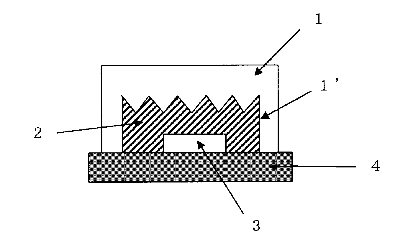
[0131]Next, the film-shaped glass piece was pulverized for 15 minutes with a stone mill and passed through a 100 micrometer sieve to obtain a glass powder (D50: 14 μm, Dmax: 145 μm). A barium silicate-based yellow phosphor powder was added to the obtained glass powder to form a powder mixture, and the powder mixture was press molded into a tablet, thereby obtain...

example 2

[0138]A wavelength conversion member was produced and measured for total flux in the same manners as in Example 1 except that the atmosphere during heat treatment (sintering) to the preform was changed to an air atmosphere. The results are shown in TABLE 2.

example 3

[0139]A wavelength conversion member was produced and measured for total flux in the same manners as in Example 1 except that the average surface roughness Ra of the die was changed to 0.65 μm. The results are shown in TABLE 2.


PUM

PropertyMeasurementUnit
surface roughness Raaaaaaaaaaa
depthaaaaaaaaaa
lengthaaaaaaaaaa

Abstract

To provide a wavelength conversion member having good surface accuracy and dimensional accuracy even when processed in various shapes, and a method for manufacturing the same. A method for manufacturing a wavelength conversion member, including the steps of: subjecting a preform made of a powder mixture containing a glass powder and an inorganic phosphor powder to heat treatment, thereby obtaining a sintered powder product; and re-press molding the sintered powder product with a die.

Description

TECHNICAL FIELD[0001]This invention relates to wavelength conversion members for converting a part of the wavelengths of light emitted from a light source, such as a light-emitting diode (LED), into another wavelength, and to methods for manufacturing the same.BACKGROUND ART[0002]White LEDs are conventionally expected to be applicable for illumination purpose as next-generation light sources to replace incandescent bulbs and fluorescent lamps. LED devices, such as white LED devices, generally have a structure in which an excitation LED chip is covered with a wavelength conversion member, or a mixture of an inorganic phosphor powder and a resin, by molding. However, heat and light emitted from such an LED chip are collectively applied to a limited region of the molded cover, and thus the resin used for the molded cover may often be colored or deformed in a short time. Therefore, there arises a problem in that a change of the luminescent color occurs in a short time to shorten the lif...

Claims


Application Information

Patent Timeline
Patent Type & Authority Applications(United States)
IPC IPC(8): H01L33/50B29D11/00C09K19/02B32B3/30B32B17/10G02B1/00C03B19/06C03C12/00H01L33/48H01L33/54H01L33/56
CPCC03C3/19C03C12/00C03C14/006C03C2214/16H01L2933/0041H01L33/501Y10T428/2457C03B19/06C03B32/005C03B2201/70Y10T428/1036Y10T428/24479Y10T428/24612H01L33/505C09K2323/03
Inventor FUJITA, SHUNSUKEUMAYAHARA, YOSHIOSAKAMOTO, AKIHIKO
Owner NIPPON ELECTRIC GLASS CO LTD
Why Eureka
Try Eureka