Instrument and method for x-ray diffraction, fluorescence, and crystal texture analysis without sample preparation

a technology of crystal texture and instrument, which is applied in the direction of instruments, material analysis using wave/particle radiation, x/gamma/cosmic radiation measurement, etc., can solve the problems of destroying any water ice that msl may encounter, corresponding increases in power consumption, mass and risk, and evaporation in the low pressure environment of mars, so as to eliminate the need for sample preparation and reduce the need for power consumption. , the effect of reducing the need for sampl

Inactive Publication Date: 2011-01-13
UNIV OF MARYLAND BALTIMORE COUNTY
View PDF13 Cites 48 Cited by
  • Summary
  • Abstract
  • Description
  • Claims
  • Application Information

AI Technical Summary

Benefits of technology

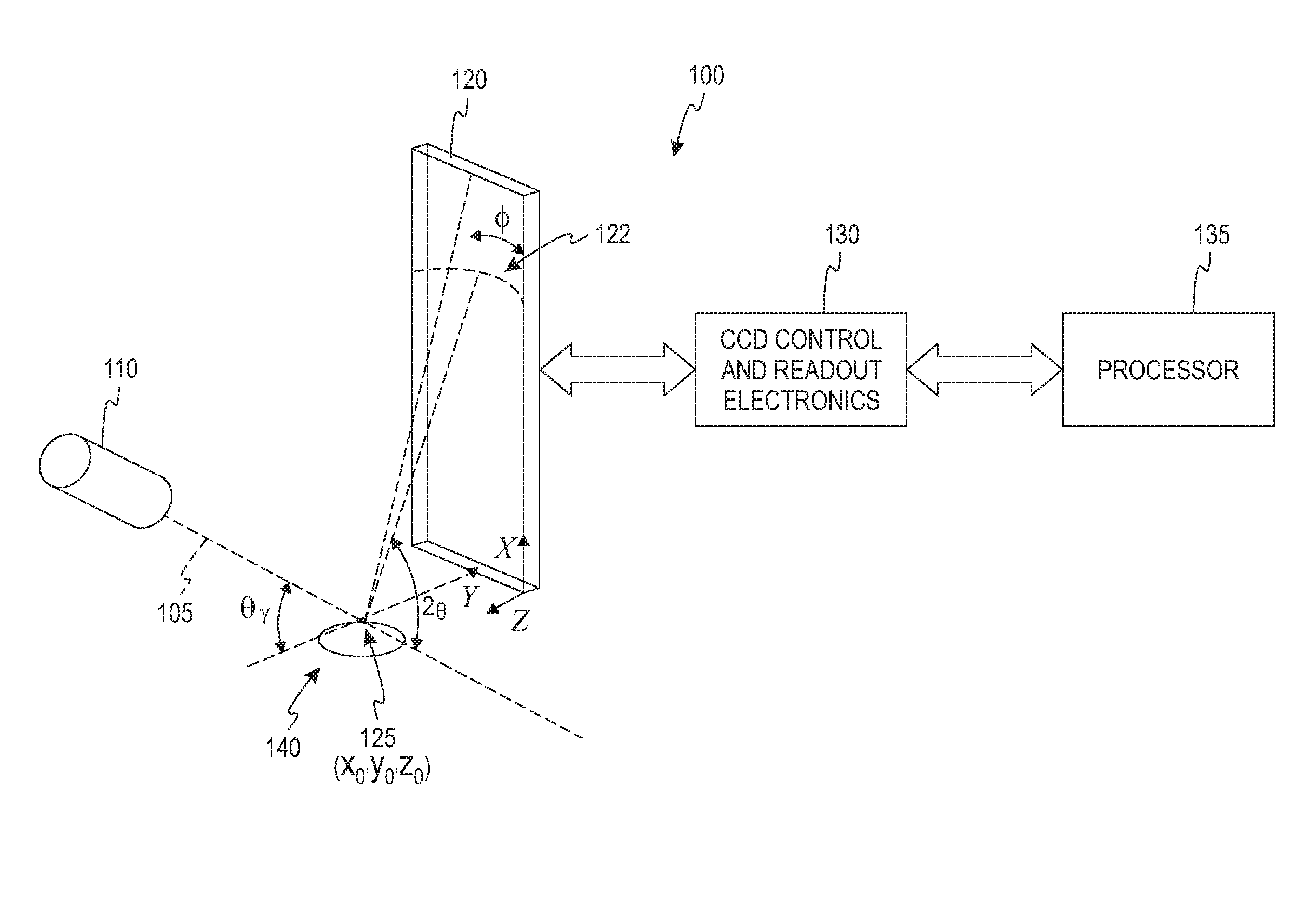
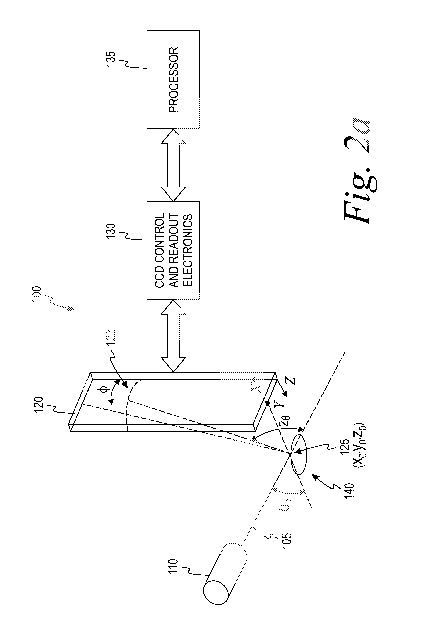
[0013]In some aspects of the present concepts, an XRD / XRF instrument and method are provided which are particularly suited for extraterrestrial applications, such as may be used in combination with a rover, landing vehicle, or craft. Such a flight-instrument application requires that the instrument be robust, lightweight, and low in power consumption. In addition, risk must be minimized whenever possible. The XRD / XRF instrument presently disclosed herein, relative to conventional XRD / XRF instruments, eliminates moving parts, eliminates sample preparation needs, provides an efficient geometry, provides improved sensitivity, and eliminates the need to place samples in vacuum, each of which improvements decrease risk and, in combination, significantly decreases risks. Further, the XRD / XRF instrument and method provided herein should provide a platform for compact and rugged packaging that consumes a minimal amount of power. It is believed that a commercial XRD / XRF instrument based on the presently disclosed instrument and methods would cost significantly less than conventional XRD / XRF instruments.
[0014]In accord with disclosed aspects of the present concepts, an instrument and method for X-ray diffraction using a reflection geometry (and the methodology presented here; e.g. continuum X-ray source, and photon counting imaging spectrometer detectors) permit measuring the atomic plane spacings of unprepared material samples. The method described herein may alternatively be implemented in a transmission geometry. Further to providing material identification, the instrument(s) and method(s) permit the determination of the crystalline grain size, domain size, and orientation distributions (i.e., crystalline texture) within samples, which provide important information on crystallographic structure, material defects, and stresses or shocks that the sample may have experienced. The new method(s) described herein are very efficient compared to standard XRD techniques (including CheMin) for mineral and chemical identification. Further, the disclosed simultaneous X-ray fluorescence analysis capability provides elemental abundances.

Problems solved by technology

However, in certain applications, such as extraterrestrial XRD analysis, the number of moving parts required increases (e.g., the CheMin device uses a carousel disc and associated drive system, sample preparation systems such as a fine-grinding mill, etc.), with corresponding increases in power consumption, mass, and risk.
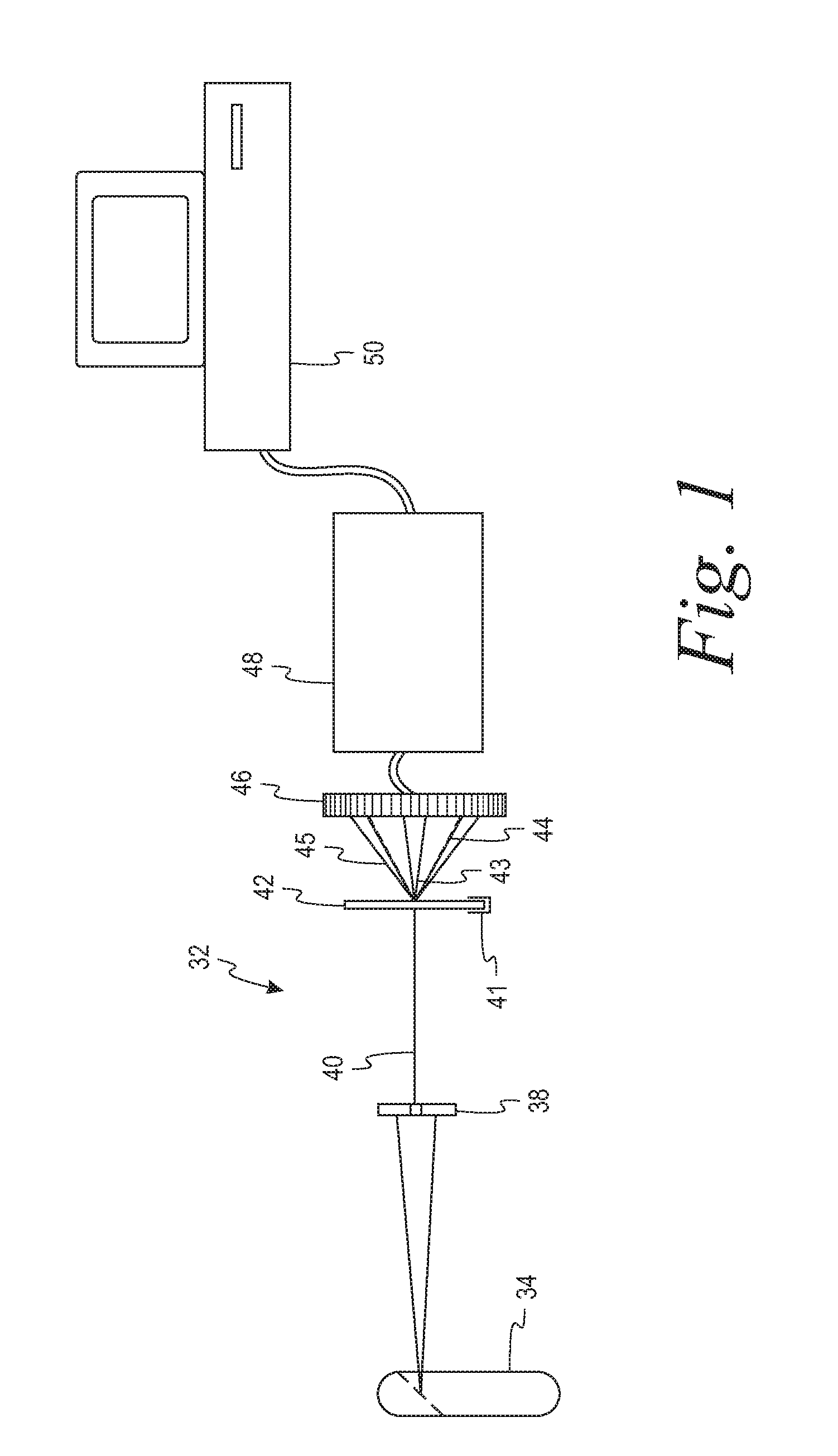
For the CheMin XRD / XRF apparatus 32, which is presently slated for inclusion on the Mars Science Laboratory (MSL) mission scheduled for launch in 2009, sample preparation is required, which would disadvantageously destroy any water ice that MSL may encounter and cause it to evaporate in the low pressure environment on Mars.
Sample preparation also destroys valuable scientific and engineering information regarding grain size and orientation distributions and evidence of stresses and shock.

Method used


Image

  • Instrument and method for x-ray diffraction, fluorescence, and crystal texture analysis without sample preparation
  • Instrument and method for x-ray diffraction, fluorescence, and crystal texture analysis without sample preparation
  • Instrument and method for x-ray diffraction, fluorescence, and crystal texture analysis without sample preparation

Examples


example 1

Al 6061

[0095]FIGS. 7a-7e show results from a piece of aluminum-6061 obtained using the second prototype XRD / XRF instrument 100 in a 2-hour data run with the X-ray source 110 operating at an electron beam current of 100 microamps. FIG. 7a shows a density plot of the photon count intensity binned in the plane of event energy vs. event diffraction angle. In this space, photons which are due to XRF (e.g., due to contaminants in this case) appear as horizontal lines 205, as shown, and photons due to XRD from crystallized regions with discrete atomic plane spacings (Miller indices) appear as arcs 210, as shown, and trace out Bragg's law for n=1. After applying Bragg's law to compute d-spacing for individual photons, the XRD arcs 210 of FIG. 7a are straightened out as vertical lines 211 in FIG. 7b, while the horizontal XRF lines 205 of FIG. 7a remain as horizontal lines 206. The XRD feature apparent at 1.73 Å is an instrument feature.

[0096]In each of FIGS. 7a-7b, several of the XRD arcs 21...

example 2

Mineral Identification

[0098]FIG. 8 shows data from a bulk sample of hematite showing both diffraction and fluorescence features. As with FIG. 7b, the hematite data is binned and plotted in the space of energy (E) vs. d-spacing, as shown in FIG. 8. XRD data is shown as vertical lines 221, while the XRF data is shown as horizontal lines 225. FIG. 8 is labeled to show some of the expected and detected diffraction features, particularly showing the d-spacings of 1.49 Å, 1.70 Å, 2.21 Å, 2.52 Å, and 2.70 Å. A faint d-spacing vertical line is also observable at 3.69 Å. FIG. 8 is also labeled to show the expected fluorescence features (e.g., Fe Kβ, Fe Kα, and Ti Kα).

[0099]Because d-spacing information acts as an effective “fingerprint” for any given mineral, the specific combination of vertical features 221 in FIG. 8 can be used to identify the sample. D-spacing values for thousands of organic and inorganic substances are available in commercial and freely available digital databases (e.g.,...

example 3

Aerosol Identification

[0103]Applications involving aerosols require a high detection limit to measure trace elements and require high sensitivity to permit analysis of minute amounts of material. A typical aerosol filter configured to collect particles on its surface (e.g., the Nuclepore® filter) holds about 20 μg / cm2 of aerosol mass. For a X-ray beam 105 having a spot size area of about 2 mm2, which is the case for the current example, the total aerosol mass observed by the beam is about 0.4 μg.

[0104]FIGS. 9a-9c show an example of an aerosol filter, analyzed using the disclosed XRD / XRF instrument 100 and techniques disclosed herein, showing measurements of at least 9 elements with X-ray fluorescence and identifying at least three major minerals in the analyzed sample (i.e., calcite, hematite, and halite). The aforementioned second prototype of the XRD / XRF instrument 100 (see generally FIG. 2b) was used to analyze data from micrograms of dust collected on a thin polycarbonate Nuclep...


PUM

PropertyMeasurementUnit
thickaaaaaaaaaa
diameteraaaaaaaaaa
angle θCaaaaaaaaaa

Abstract

An X-ray diffraction and X-ray fluorescence instrument for analyzing samples having no sample preparation includes a X-ray source configured to output a collimated X-ray beam comprising a continuum spectrum of X-rays to a predetermined coordinate and a photon-counting X-ray imaging spectrometer disposed to receive X-rays output from an unprepared sample disposed at the predetermined coordinate upon exposure of the unprepared sample to the collimated X-ray beam. The X-ray source and the photon-counting X-ray imaging spectrometer are arranged in a reflection geometry relative to the predetermined coordinate.

Description

CROSS-REFERENCE TO RELATED APPLICATION[0001]This application is a continuation of, and claims benefit of priority to, U.S. patent application Ser. No. 11 / 706,693 filed Feb. 14, 2007, entitled “Instrument And Method For X-ray Diffraction, Fluorescence, And Crystal Texture Analysis Without Sample Preparation”, and U.S. Provisional Patent Application No. 60 / 773,244 filed on Feb. 14, 2006, entitled “Instrument And Method For X-ray Diffraction, Fluorescence, And Crystal Texture Analysis Without Sample Preparation” and U.S. Provisional Application No. 60 / 776,576 filed on Feb. 24, 2006, entitled “Instrument And Method For X-ray Diffraction, Fluorescence, And Crystal Texture Analysis Without Sample Preparation” all of which is hereby incorporated by reference in its entirety.STATEMENT REGARDING FEDERALLY SPONSORED RESEARCH OR DEVELOPMENT[0002]The described herein was made in the performance of work under a NASA contract or grant and by employees of the United States Government and is subjec...

Claims


Application Information

Patent Timeline
Patent Type & Authority Applications(United States)
IPC IPC(8): G01N23/223
CPCG01N23/20G01N2223/076G01N23/223
Inventor GENDREAU, KEITHMARTINS, JOSE VANDERLEIARZOUMANIAN, ZAVEN
Owner UNIV OF MARYLAND BALTIMORE COUNTY
Why Eureka
Try Eureka