Catalytic electrode with gradient porosity and catalyst density for fuel cells

Active Publication Date: 2011-01-13
FLORIDA STATE UNIV RES FOUND INC
View PDF21 Cites 13 Cited by
  • Summary
  • Abstract
  • Description
  • Claims
  • Application Information

AI Technical Summary

Benefits of technology

[0011]The microstructure of the LBP can be tailored by adjusting the starting materials and nanoparticle dispersion so as to achieve a desired porosity, pore size, surface area, and electrical conductivity for use as the catalyst layer of the MEA. The catalyst nanoparticles are preferably deposited directly at the most ef

Problems solved by technology

One obstacle to achieving this aim, however, is the fact that conventional catalyst supporting materials, such as carbon black Vulcan XC-72R, have numerous micropores in which Pt nanoparticles can become trapped.
This typically results in a failure in establishing the three-phase boundary (TPB) among gas, electrolytes, and the electrocatalyst of a fuel cell.
Moreover, carbon black can be corroded under th

Method used


Image

  • Catalytic electrode with gradient porosity and catalyst density for fuel cells
  • Catalytic electrode with gradient porosity and catalyst density for fuel cells
  • Catalytic electrode with gradient porosity and catalyst density for fuel cells

Examples


example 1

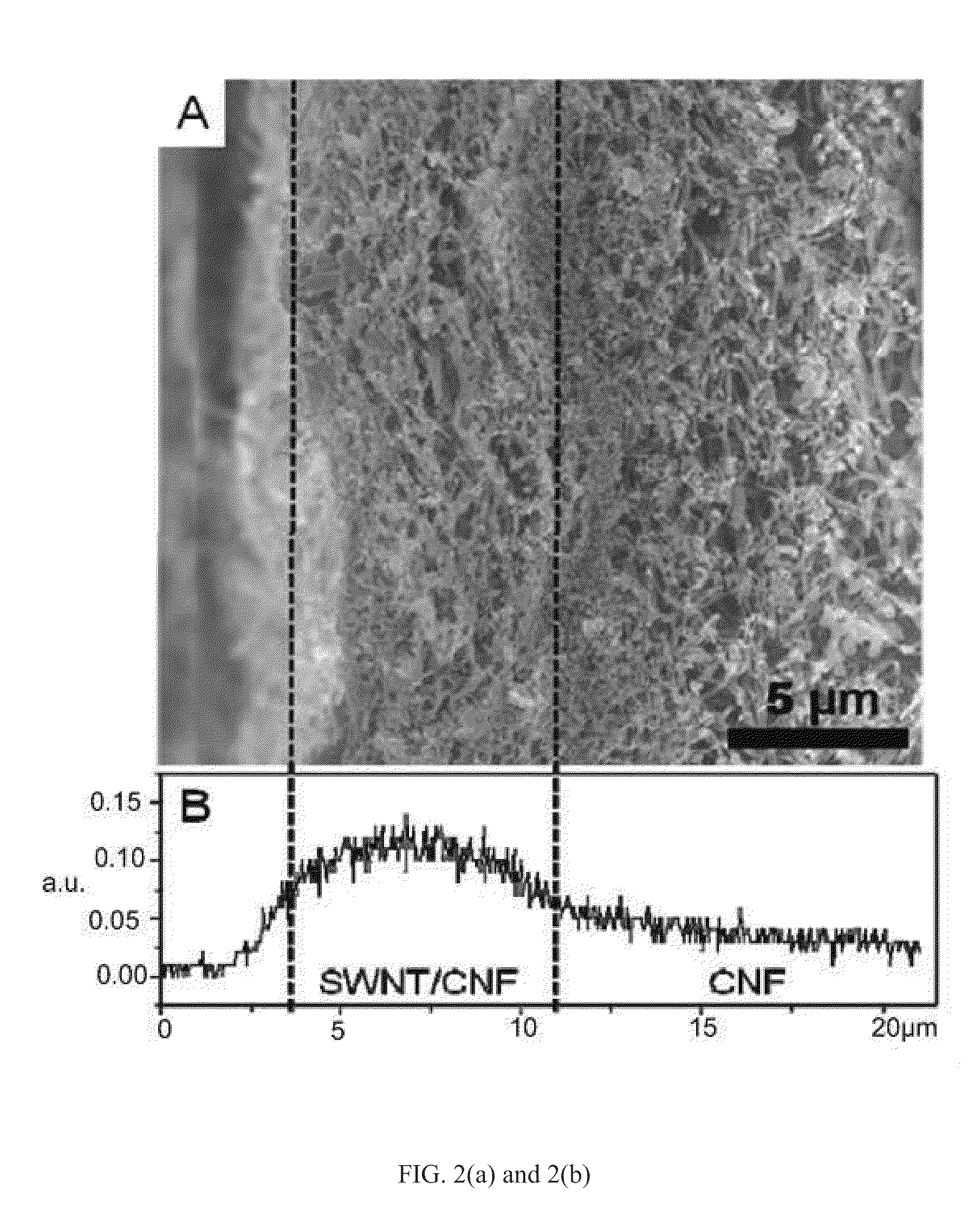
[0058]An exemplary gradient catalyst structure was prepared by filtrating a 25 wt-% SWNT / 75 wt-% CNF suspension and CNF suspension sequentially under full vacuum. As shown in FIG. 2(a), the CNFs entangle randomly forming a highly porous second layer with a porosity of 90.8% and an average pore size of 85 nm, while smaller pores are formed in the SWNT / CNF layer by adding 25 wt. % fine-sized SWNTs. As a result, the SWNT / CNF first layer has a much larger surface area (105 m2 / g) than that of the CNF layer (24 m2 / g) because of the high aspect ratio of SWNT. After depositing Pt on the layered buckypaper by electrochemical deposition, EDS analysis in FIG. 2(b) showed a gradient distribution of Pt, with over 70% of the Pt distributed in the 7-micron-thick SWNT / CNF first layer. As shown in FIGS. 2(c) and 2(d), a large amount of Pt deposited on the surface of the SWNT / CNF first layer while fewer Pt nanoparticles deposited an the surface of the CNF second layer. Thus, FIG. 2 provides a qualita...

example 2

[0061]The Pt / LBP with tailored gradient structure has demonstrated promising Pt utilization and stability of supports in spite of relative large Pt particle size. Considering the negligible improvement of anodic oxygen reduction reaction (ORR) activity by using Pt / LBP, such high cell performance is believed to result from the inventive microstructure of the gradient catalyst structure. To evaluate the effect of the microstructure on the fuel cell performance, two conventional single-layer buckypaper MEAs were compared in terms of their polarization curve and electrochemical impedance (EIS). The conventional buckypapers consist of the mixture of SWNT and CNF in a weight ratio of 1:3 (described as SF13) or 1:9 (described as SF19) with a thickness of 14 μm. Pt was deposited on each of the conventional buckypapers and the Pt / LBP layered buckypaper under the same conditions, consequently each had nearly the same catalyst nanoparticle size. Nafion was impregnated on the conventional bucky...

example 3

[0064]In W. Zhu et al., Durability Study on SWNT / Nanofiber Buckypaper Catalyst Support for PEMFCs, Journal of the Electrochemical Society (2009), a SWNT / CNF buckypaper with Pt catalyst nanoparticles demonstrated good durability under an accelerated degradation test in a simulated PEM fuel cell cathode environment. The good durability is believed to be due to the high corrosion resistance resulting from the high degree of graphitization of the CNFs. Subsequently, the durability of catalyst support for the Pt / LBP-based MEA disclosed herein was evaluated per DOE's test protocol set forth in U.S. Dept. of Energy, Hydrogen, Fuel Cell &Infrastructure Technologies Program Multi-Year Research, Development and Demonstration Plan (2007). FIG. 5 shows the polarization curves at different time intervals during the 200-hour durability test. The mass activity measured at 900 mV lost only 57.6% of initial activity after 200 hours of operation, which is much better than that obtained in conventiona...


PUM

PropertyMeasurementUnit
Weightaaaaaaaaaa
Efficiencyaaaaaaaaaa
Porosityaaaaaaaaaa

Abstract

A membrane electrode assembly (MEA) for a fuel cell comprising a gradient catalyst structure and a method of making the same. The gradient catalyst structure can include a plurality of catalyst nanoparticles, e.g., platinum, disposed on layered buckypaper. The layered buckypaper can include at least a first layer and a second layer and the first layer can have a lower porosity compared to the second layer. The gradient catalyst structure can include single-wall nanotubes, carbon nanofibers, or both in the first layer of the layered buckypaper and can include carbon nanofibers in the second layer of the layered buckypaper. The MEA can have a catalyst utilization efficiency of at least 0.35 gcat/kW or less.

Description

CROSS REFERENCE TO RELATED APPLICATIONS[0001]This application claims priority to U.S. Provisional Application No. 61 / 320,639, entitled “Catalytic Electrode with Gradient Porosity and Catalyst Density for Fuel Cells,” filed Apr. 2, 2010, and is a Continuation-in-Part of U.S. patent application Ser. No. 12 / 505,070, entitled “Carbon Nanotube and Nanofiber Film-Based Membrane Electrode Assemblies,” filed Jul. 17, 2009, which claims priority to U.S. Patent Application No. 61 / 081,851, entitled “Carbon Nanotube and Nanofiber Film-Based Membrane Electrode Assemblies,” filed Jul. 18, 2008, and is a continuation-in-part of U.S. patent application Ser. No. 11 / 670,687, filed Feb. 2, 2007, which claims priority to U.S. Patent Application No. 60 / 764,504, filed Feb. 2, 2006, the entirety of each is incorporated herein by reference.STATEMENT REGARDING FEDERALLY SPONSORED RESEARCH OR DEVELOPMENT[0002]The United States Government has rights in this invention pursuant to contract no. 023106 between th...

Claims


Application Information

Patent Timeline
IPC IPC(8): H01M8/10
CPCH01M4/92H01M4/926H01M8/0234H01M8/1004C04B2235/5288H01M4/8807B82Y30/00H01M8/0245H01M4/8892H01M4/8657H01M4/8642Y02E60/521Y02P70/50Y02E60/50H01M4/90B01J23/00B82B3/00H01M4/88
Inventor ZHENG, JIAN-PINGLIANG, ZHIYONGWANG, BENZHANG, CHUNZHU, WEI
Owner FLORIDA STATE UNIV RES FOUND INC
Why Eureka
Try Eureka