
Adiabatic external combustion with low pressure positive displacement motor

a positive displacement, external combustion technology, applied in the direction of machines/engines, positive displacement liquid engines, flexible member pumps, etc., can solve the problems of poor efficiency, high fuel consumption, bulky size,

Inactive Publication Date: 2011-01-20
BENHAM ROGER A
View PDF24 Cites 7 Cited by
  • Summary
  • Abstract
  • Description
  • Claims
  • Application Information

AI Technical Summary

Benefits of technology

[0021]The present invention is directed to an improved external combustor and device for providing pressurized gas to conduct work, such as, but not limited to, driving a low-pressure-gradient positive displacement motor to produce rotational power output. For example, the external combustor described can provide heated and pressurized gas to any pressure-driven motor such as a rotary gear, rotary vane, turbine, or piston driven motor. Additionally, the external combustor and the low pressure-gradient positive displacement motor can be combined to produce a device for energy storage and regenerative braking, which may at least partially overcome the deficiencies in the prior art or provide the consumer with a useful or commercial choice.
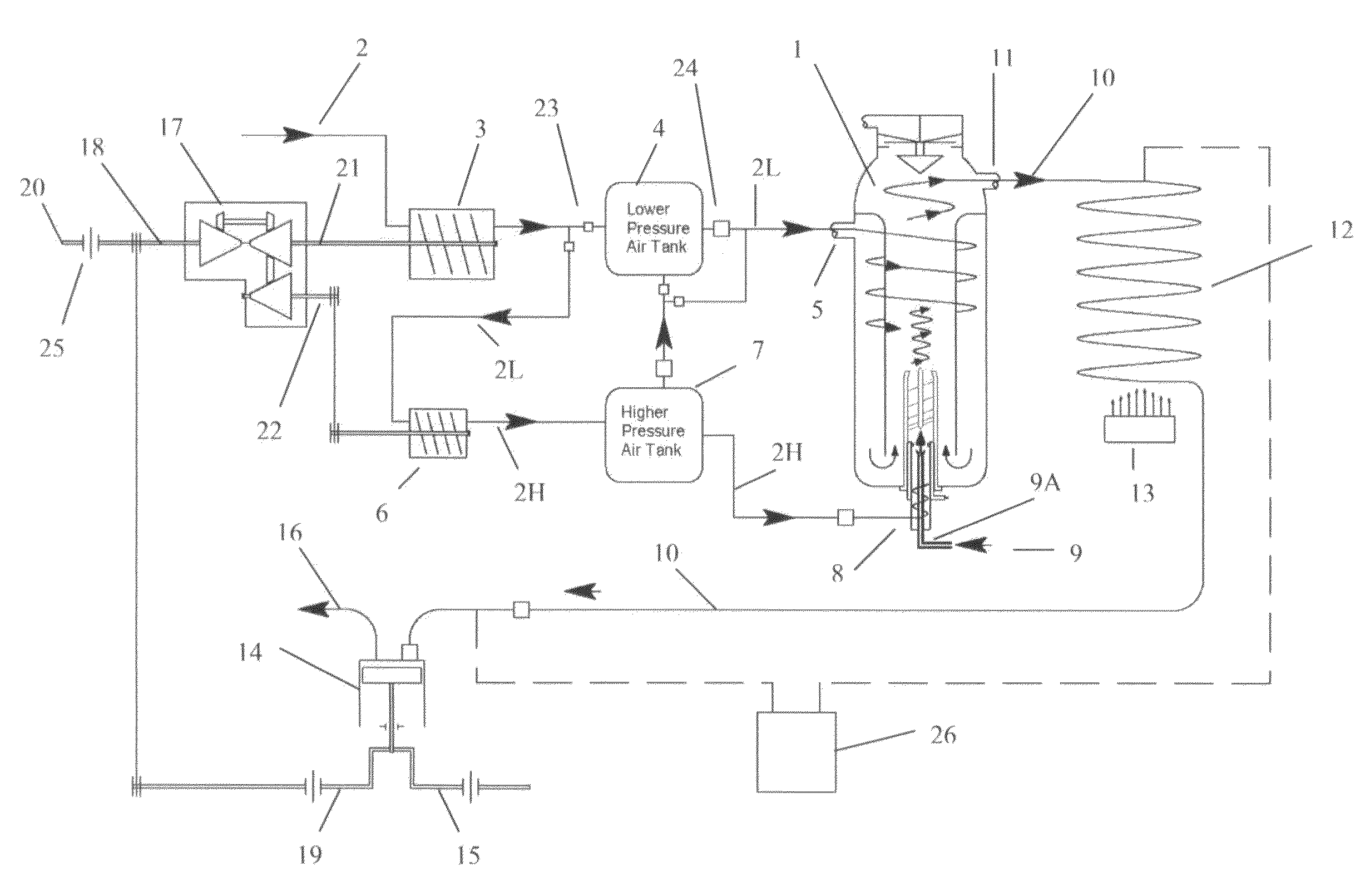
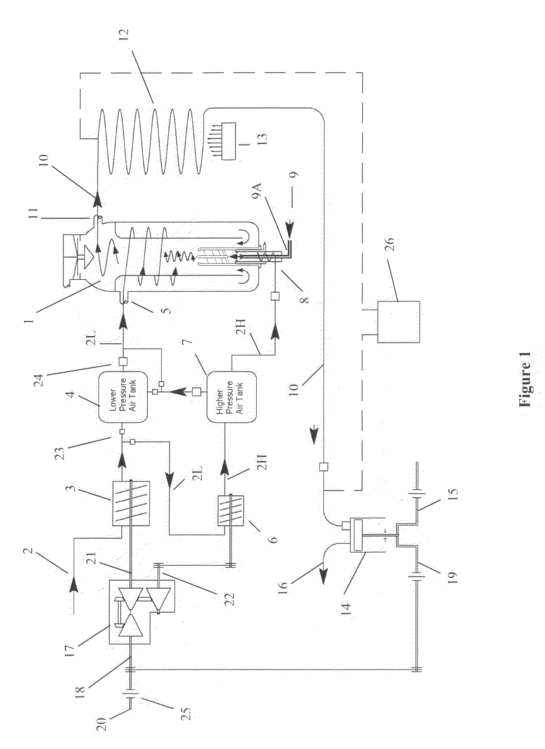
[0022]The combustion takes place in a separate pressurized combustion vessel that is supplied with a liquid, solid, gas or combination thereof organic fuel and two separate streams of compressed air, one from a lower pressure air compressor and one from a higher pressure air compressor. The combustion gases produced by igniting the fuel with the higher pressure air stream are accelerated and blended with the lower pressure air stream in a manner to produce a mixture of a high temperature pressurized working gas. The design includes features of regenerative cooling of the combustion vessel, improved combustion characteristics, and higher efficiency. In the preferred embodiment, the device for providing the compressed air to the lower and higher pressure air receivers is accomplished by an axial or screw-type compressor interconnected to a demand-controlled continuously variable transmission driven by the output motor, an ancillary motor, or the driving or braking force of the drivetrain of a vehicle. Usable power is produced by combining the blended combustion products from the external combustion apparatus to a low pressure-gradient positive displacement motor to produce rotational power output.
[0023]It is an object of the present invention to provide a combustion apparatus which may overcome at least some of the abovementioned disadvantages, or provide a useful or commercial choice.
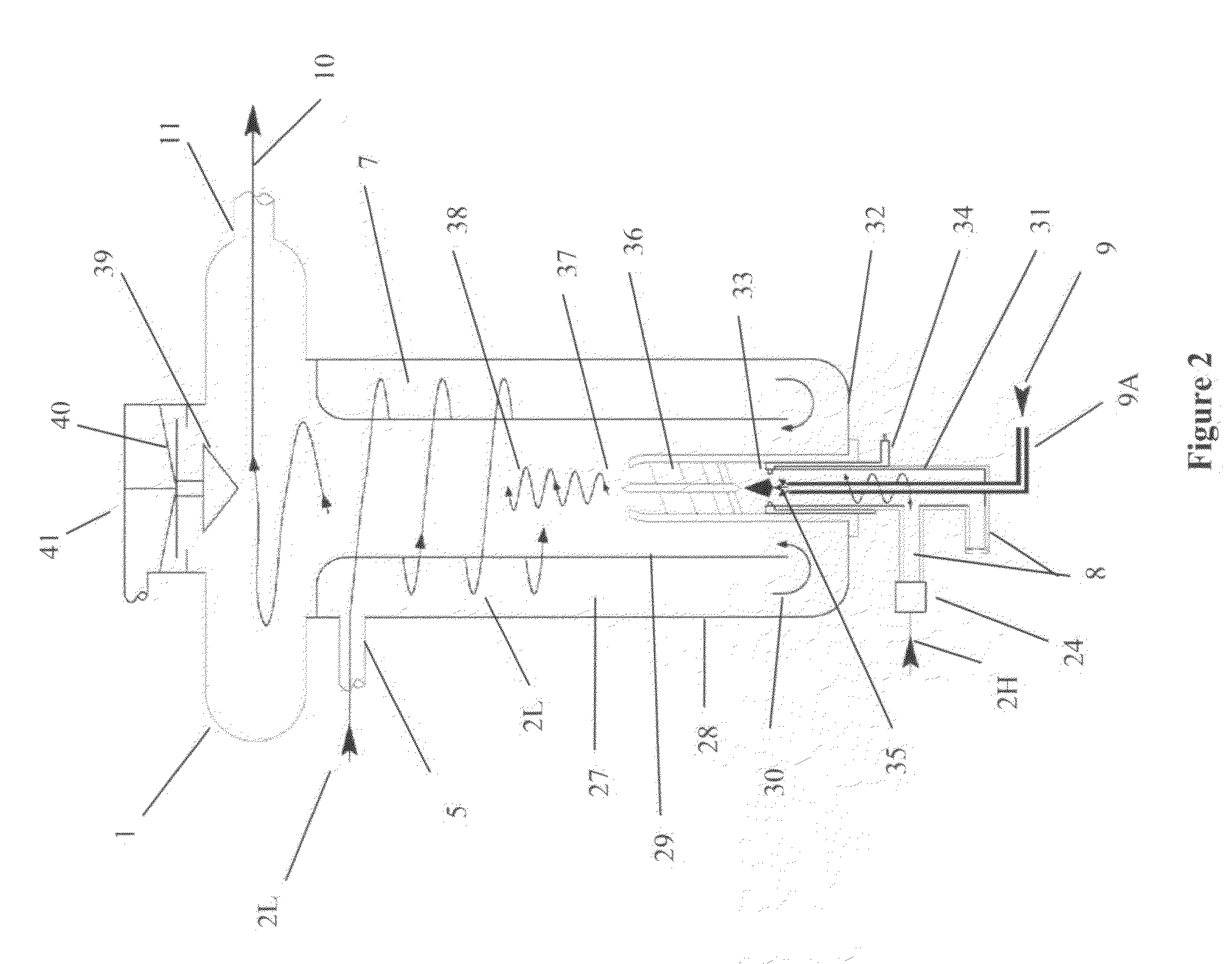
[0027]The upper inlet may be of any suitable type or configuration. Preferably, however, the upper inlet is adapted to provide an entry for the lower pressure gas stream into the combustion vessel such that the lower pressure gas stream rotates within the combustion vessel at or adjacent an inner surface of the combustion vessel. In some embodiments of the invention, the upper inlet is adapted to provide an entry point for the first lower pressure gas stream that is tangential to the wall of the combustion vessel. In this embodiment of the invention, it is preferred that the combustion vessel is substantially cylindrical so as to provide the most suitable vessel geometry for the lower pressure gas stream to rotate within the combustion vessel at or adjacent an inner surface of the outer wall of the vessel. In this way, the lower pressure gas stream may form a curtain or skirt of gas adjacent the inner surface of the outer wall of the vessel, thereby cooling the outer wall of the combustion vessel. In addition, a constant flow of the lower pressure gas stream through the upper inlet ensures that the regenerative cooling of the inner flow skirt of the combustion vessel occurs due to no recycling of the lower pressure blending gas stream taking place.
[0032]The higher pressure combustion gas stream and the fuel may be combined prior to entering the vessel such that a combined fuel / higher pressure combustion gas stream enters through the lower inlet. Alternatively, the higher pressure combustion gas stream and the fuel may be combined in a passageway leading to the lower inlet using any suitable technique (such as a Venturi effect to draw the fuel into the lower inlet). In other embodiments of the invention, the lower inlet may be provided with an inlet passageway, the inlet passageway having a fuel inlet and a higher pressure combustion gas stream inlet. In this embodiment of the invention, the fuel and higher pressure combustion gas stream may be allowed to combine at any suitable point within the inlet passageway. However, in a preferred embodiment of the invention, the fuel and higher pressure combustion gas stream may only be combined at or near the point of entry into the combustion chamber. In this way, any premature reaction of the fuel and higher pressure combustion gas stream may be prevented. This may be important both from a safety point of view, and in terms of ensuring that as much energy generated by the reaction of the fuel and the higher pressure combustion gas stream is captured within the combustion vessel.
[0042]In some embodiments of the invention, the combustion vessel may be provided with a pressure relief device. In this way, if the pressure inside the combustion vessel reaches a predetermined upper limit, the pressure relief device may be activated in order to reduce the pressure within the combustion vessel, thereby preventing damage to the apparatus, or an explosion, or the like. Any suitable pressure relief device may be provided, such as but not limited to, one or more seals, valves, springs or the like that is activated when the pressure reaches a predetermined level, thereby causing depressurization of the combustion vessel.

Problems solved by technology

While engines of this kind have become widely used, they suffer from a number of drawbacks, including their bulky size, poorer efficiency, higher fuel consumption, higher level of hazardous emissions (such as nitrous oxides and carbon monoxide) and the higher cost of construction.
In addition, conventional internal combustion engines are adapted to run on a single type of fuel only, making them relatively inflexible.
However, these devices suffer from the drawbacks of having lower efficiency (including failing to recover waste heat), require combustion to occur at high temperatures, require cooling and do not provide for such typical vehicle conditions such as idling or instant starting.

Method used


Image

  • Adiabatic external combustion with low pressure positive displacement motor
  • Adiabatic external combustion with low pressure positive displacement motor
  • Adiabatic external combustion with low pressure positive displacement motor

Examples


operation examples

Idle Operation

[0077]Under typical conditions there would be no idling or combustion when the vehicle is stopped, similar to an electric or hybrid vehicle. The whole system would not operate when at a stop, and would remain in a standby mode with the supply of compressed air in the air storage tanks 4, 7 ready for initial acceleration. There may be conditions where the external combustor 1 and low pressure-gradient positive displacement motor will run when the vehicle is at a full stop, for example, when it is necessary for heating or air conditioning, or when it is desired to fill the air storage tanks with compressed air for later use.

Acceleration

[0078]The external combustor 1 is not required to operate during initial acceleration because the energy to accelerate the vehicle from a dead stop could come from the pressurized air in the storage tanks 4,7 similar to the operation of an air motor. After the vehicle gets up to speed, combustion air and fuel can be injected into the ignit...


PUM


Abstract

The present invention relates to a method and device using an external combustion apparatus to supply large amounts of heated and pressurized combustion gases used to produce mechanical movement of a device, such as, but not limited to, a piston or a low pressure positive displacement motor. The combustion takes place in a separate pressurized combustion vessel that is supplied with organic fuel and two separate streams of compressed air, one from a lower pressure air receiver and one from a higher pressure air receiver. The combustion gases from igniting the fuel with the higher pressure air stream are accelerated and blended with the lower pressure air stream in a manner to produce a mixture of higher temperature pressurized working gas. The design includes features of regenerative cooling of the combustion vessel, improved combustion characteristics, regenerative breaking, and higher efficiency.

Description

CROSS-REFERENCE TO RELATED APPLICATIONS[0001]The present invention claims the benefit of the filing date of U.S. provisional patent application Ser. No. 61 / 213,782, filed Jul. 14, 2009. The present invention is also a continuation-in-part of U.S. patent application Ser. No. 12 / 659,835, filed on Mar. 23, 2010, and incorporates the subject matter therein by reference.FIELD OF THE INVENTION[0002]The present invention relates to a means of using an external combustion apparatus to supply large amounts of heated and pressurised combustion gases to an output device, such as, but not limited to, a low pressure-gradient positive displacement motor to provide a pressure differential on opposing sides of a membrane in the motor to produce a rotational power output.BACKGROUND OF THE INVENTION[0003]In conventional combustion apparatus, such as those used to provide the driving force to vehicles and the like, the combustion apparatus is an engine in which combustion takes place internally to the...

Claims


Application Information

Patent Timeline
IPC IPC(8): F02B43/00
CPCF04B43/023
Inventor BENHAM, ROGER A.
Owner BENHAM ROGER A
Learn More