Collaborative Environment For Physical Verification Of Microdevice Designs

a technology for physical verification and microdevices, applied in the field of collaborative environment for physical verification of microdevices, can solve the problems of increasing the difficulty of physical verification, affecting the quality of physical verification, so as to facilitate collaboration

Active Publication Date: 2011-01-20
SIEMENS PROD LIFECYCLE MANAGEMENT SOFTWARE INC
View PDF37 Cites 16 Cited by
  • Summary
  • Abstract
  • Description
  • Claims
  • Application Information

AI Technical Summary

Benefits of technology

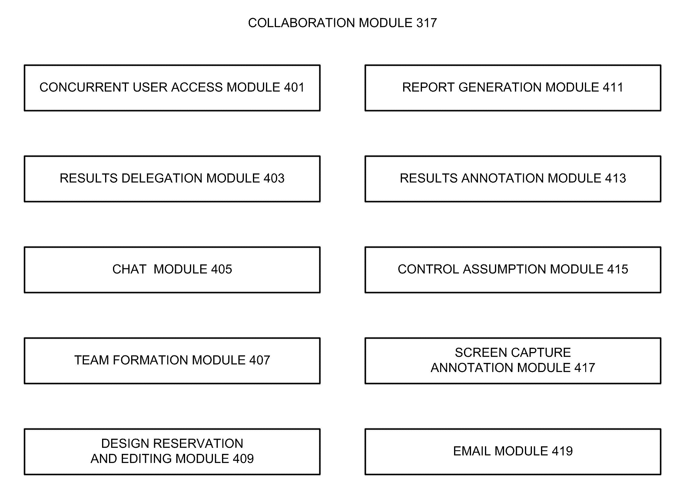
[0081]With various examples of the invention, the report generation module 411 may be used to create reports that include design errors, waived design problems, fixed design problems or some combination thereof. Some implementations of the invention will allow multiple standard formats of reports to be created, with users being able to share these reports. With some examples of the invention, each report may be saved in a “reports” section of the hierarchical database 305 or in a separate design database/directory for easy reference by other team members. Various examples of the invention may allow a user (e.g., a team member) to send the “link” of a report to a specified destination or person, or extract it in HTML, RTF of PDF for inclusion in other documentation.
[0082]A report generation module 411 according to various examples of the invention may allow a user to view issues with the design in a convenient manner that supports cross selection of similar or related issues in the document, in addition to the original design, if it has not been altered. With some implementations of the invention, this functionality may be accessed like a book, with multiple “pages” describing different issues. A list of issues may be displayed, or all issues from one cell or geographic region of the design, for example. Also, with various examples of the invention, the report generation module 411 may allow a user to save multiple named reports for re...

Problems solved by technology

Moreover, the sizes of the polygons are limited physically by the maximum beam aperture size available to the tool.
As the design teams begin to assemble their physical layout design blocks into a design for the entire integrated circuit, however, the task of physical verification becomes more difficult.
New errors can appear in the con...

Method used


Image

  • Collaborative Environment For Physical Verification Of Microdevice Designs
  • Collaborative Environment For Physical Verification Of Microdevice Designs
  • Collaborative Environment For Physical Verification Of Microdevice Designs

Examples


Embodiment Construction

Illustrative Operating Environment

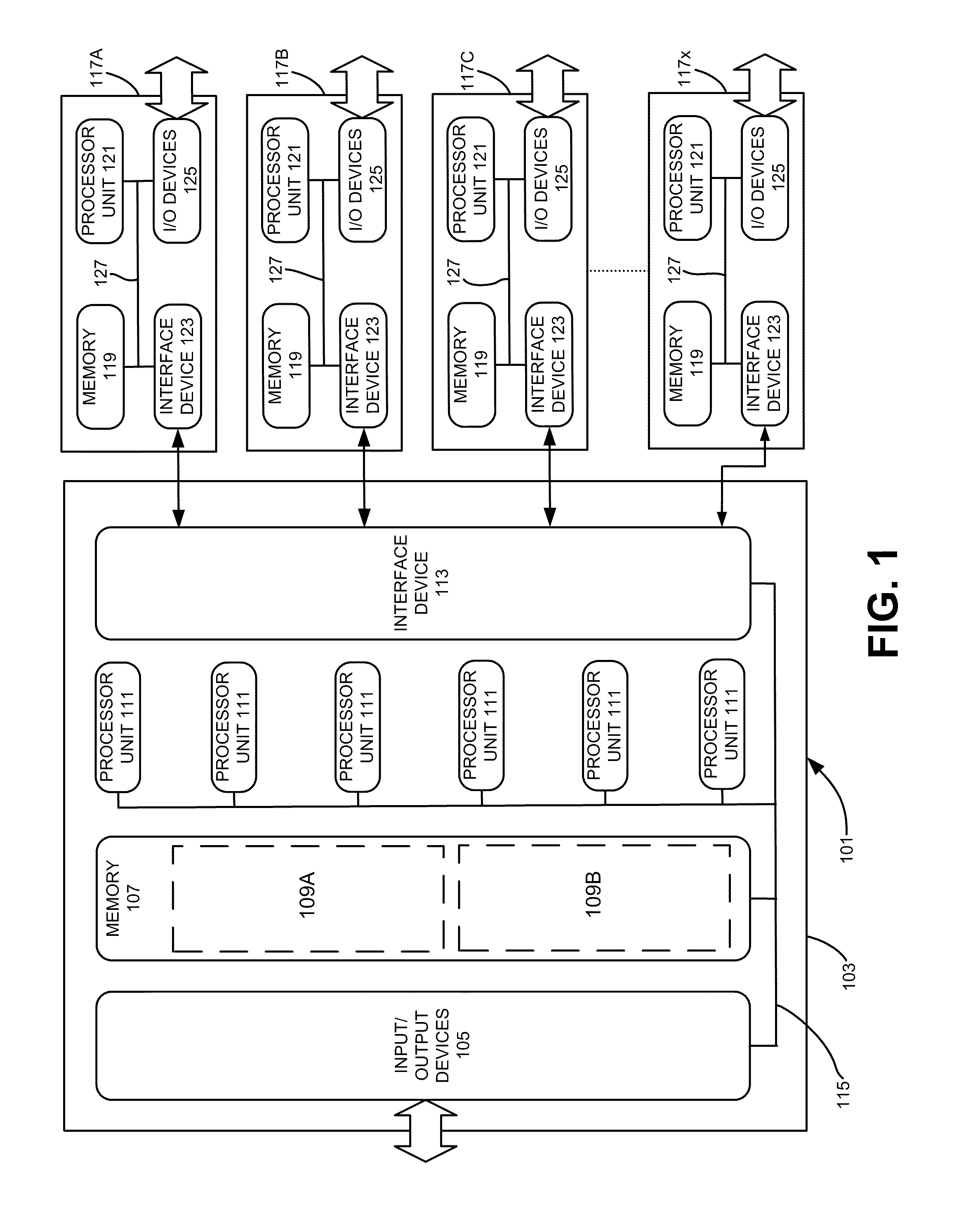
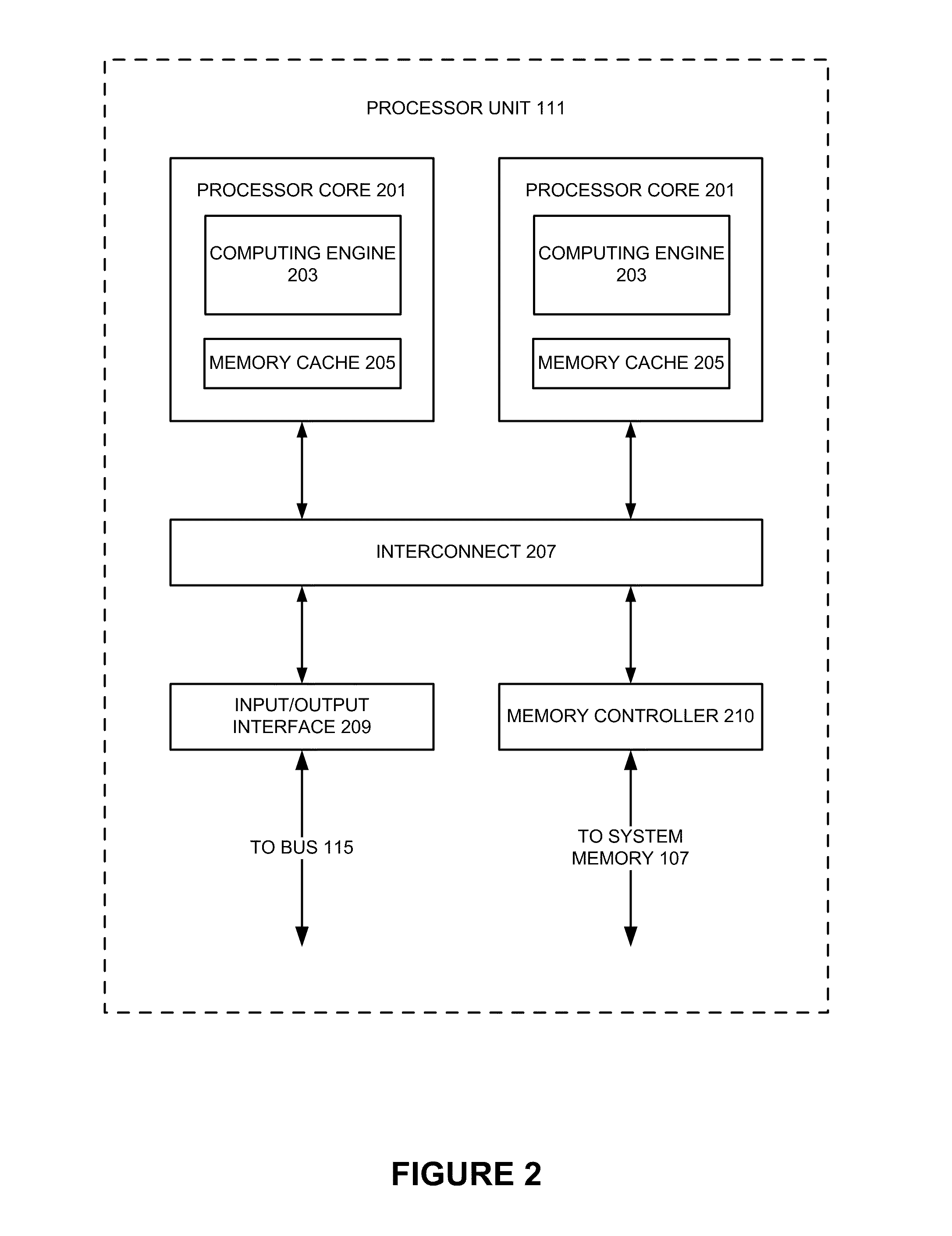
[0021]Various examples of a collaborative environment for one or more electronic design automation processes according to embodiments of the invention may be implemented by one or more programmable computing devices executing computer-executable software instructions. Alternately or additionally, various examples of a collaborative environment for one or more electronic design automation processes according to embodiments of the invention may be implemented by computer-executable software instructions stored in a computer-readable medium, such as a magnetic or optical storage device, or a solid state memory device. Because these embodiments of the invention may be implemented using software instructions, the components and operation of a generic programmable computer system through which various embodiments of the invention may be employed will first be described.

[0022]Further, because of the complexity of some electronic design automation processes...


PUM


Abstract

A collaborative environment for performing physical verification processes on integrated circuit designs. Multiple physical verification results may be stored in a “unified” results database/directory (e.g., unified at least from a user's perspective), where results from various verification processes, such as Design-Rule-Check (DRC) processes, Layout-Versus-Schematic comparison (LVS) processes, Design-For-Manufacturing (DFM) processes Optical Proximity Correction (OPC) processes, and Optical Rule Check (ORC) processes are accessible from the same style of user interface, which may be a graphical user interface. The basic abilities for design team-based interactions can be equally available to each process involved in the physical verification of an integrated circuit design.

Description

RELATED APPLICATIONS[0001]This application claims priority under 35 U.S.C. §119 to U.S. Patent Application No. 61 / 153,640, filed on Feb. 18, 2009, entitled “Team Debug For Physical Verification Of Integrated Circuit Designs” and naming William M. Hogan, James M. Paris and John G. Ferguson as inventors, which application is incorporated entirely herein by reference.FIELD OF THE INVENTION[0002]The present invention is directed to aspects of electronic design automation tools for verifying physical designs of microdevices, such as integrated circuit devices. Various implementations of the invention allow multiple designers to collaborate on one or more processes related to verifying a physical design, such as layout-versus-schematic processes, design rule check processes, design for manufacturing processes, optical proximity correction processes, and optical rules check processes. With some implementations of the invention, multiple designers may be provided concurrent access to view, ...

Claims


Application Information

Patent Timeline
IPC IPC(8): G06F17/50
CPCG06Q10/10G06F17/5081G06F30/398
Inventor PARIS, JAMES M.HOGAN, WILLIAM M.FERGUSON, JOHN G.
Owner SIEMENS PROD LIFECYCLE MANAGEMENT SOFTWARE INC
Why Eureka
Try Eureka