

Refrigerant Composition
a technology of refrigerant composition and composition, applied in the direction of heat exchange elements, chemistry apparatuses and processes, etc., can solve the problems of deterioration of lubricity, incompatibility with mineral oil, safety, performance, convenience, etc., and achieve the effect of small global warming potential, excellent cooling performance, and non-toxi
- Summary
- Abstract
- Description
- Claims
- Application Information
AI Technical Summary
Benefits of technology
Problems solved by technology
Method used
Image

Examples
examples
[0036]The present invention will be described with reference to examples hereinbelow in detail, however the present invention is not limited within these examples.
Solubility Test of Dimethyl Ether / Carbon Dioxide
[0037]In order to know solubility of a mixture system of dimethyl ether (DME) and carbon dioxide (CO2), and in order to obtain coefficient of performance of the mixed refrigerant in the refrigerant cycle system described hereinbelow, a solubility test of DME / CO2 was performed. The test method is as follows.
(1) 300 g of dimethyl ether was encapsulated and sealed in a 500-mL pressure vessel, and weight of the sealed vessel was measured by using electric weighing machine.
(2) The pressure vessel was set in the constant-temperature bath and kept at a constant temperature.
(3) Carbon dioxide was injected by using a booster pump until obtaining a constant pressure.
(4) Weight of the filled carbon dioxide was calculated by weighing before and after filling (d=0.1 g).
[0038]In the fillin...
first example
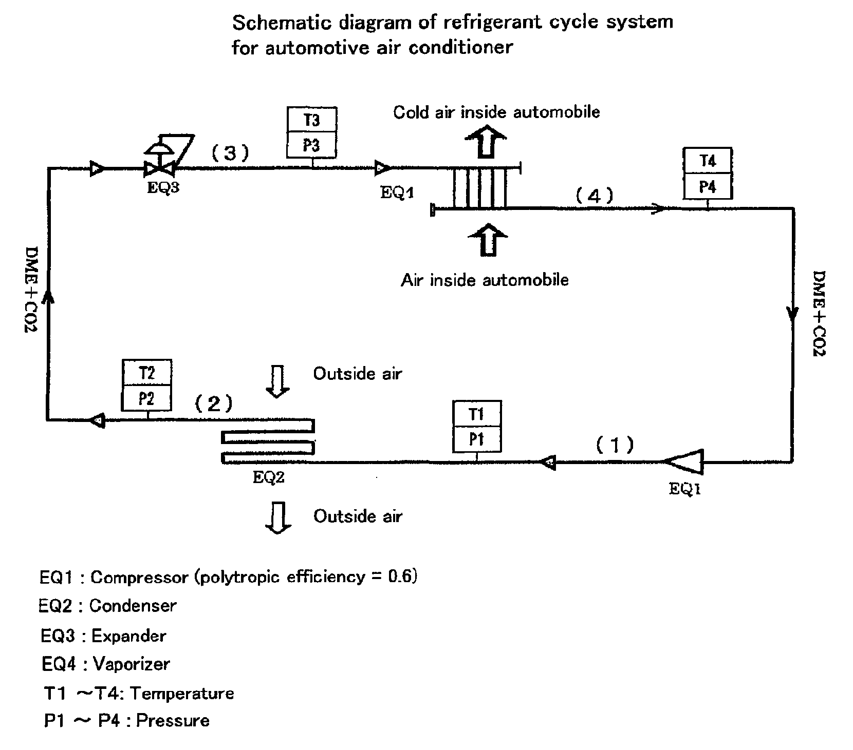
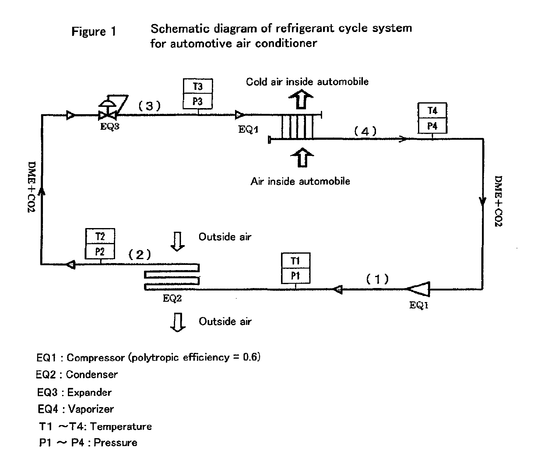
[0041]Coefficient of performance (COP) of the mixed refrigerant of dimethyl ether and carbon dioxide in the refrigerant cycle system shown in FIG. 1 was obtained. Simulation using the simulation system for the numerical chemical process was performed by following operation procedure.
Simulation Procedure
[0042]A quantity of state of stream (1) to (4) (volume, enthalpy, entropy, etc.) in the refrigerant cycle system in FIG. 1 was determined by simulation to obtain coefficient of performance (COP) of the following equation.
COP=H1 / H2
[0043]H1: total amount of exhaust heat of refrigerant in condenser
[0044]H2: amount of power of compressor from (4) to (1)
[0045]Condition setting was as follows.
(1) DME / CO2 Mixed Refrigerant
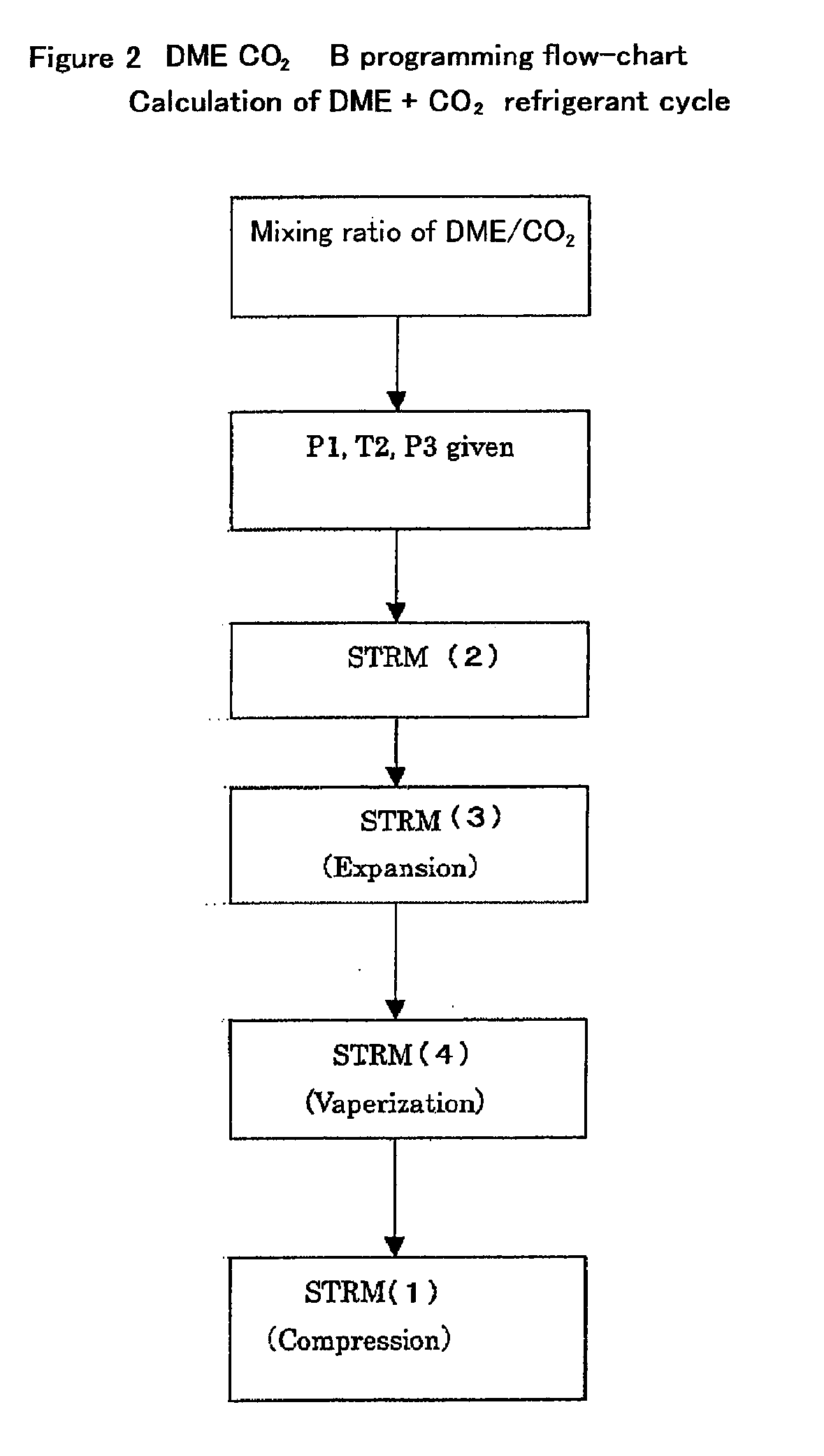
[0046]In order to evaluate cooling ability of a DME / CO2 mixed refrigerant, the discharge pressure of the compressor, the outlet temperature of the condenser, the pressure of the vaporizer and the mixing ratio of DME / CO2 were used as fluctuating parameter for calculation.
P1=...
example 1
[0064]In order to evaluate cooling ability of a dimethyl ether / carbon dioxide mixed refrigerant, simulation was performed by using the discharge pressure of the compressor, the outlet temperature of the condenser, the pressure of the vaporizer and the mixing ratio of DME / CO2 as fluctuating parameter for calculation. In the simulation, the outlet temperature of the condenser T2 was set at 32° C., and the pressure of the vaporizer was set at 3.1 MPa. Hereinbelow, simulation results of cooling characteristics in each DME / CO2 mixing ratio (% by mole) are shown. In the following table, “condensation ratio” indicates a molar ratio of the gas phase and the liquid phase in the condenser outlet, “gas %” indicates a gas phase molar fraction of the refrigerant in the expander outlet, and “liquid %” indicates a liquid phase molar fraction of the refrigerant in the expander outlet. In the table, “inlet / outlet” of the vaporizer temperatures indicate temperatures of the refrigerator in the inlet a...
PUM
| Property | Measurement | Unit |
|---|---|---|
| critical temperature | aaaaa | aaaaa |
| critical pressure | aaaaa | aaaaa |
| temperature | aaaaa | aaaaa |
Abstract
Description
Claims
Application Information