After-treatment apparatus for exhaust gas in a combustion chamber

a technology of exhaust gas and aftertreatment apparatus, which is applied in the direction of mechanical equipment, electric ignition installation, machines/engines, etc., can solve the problems of poor mileage of internal combustion engine, poor air-to-fuel ratio, excessive afterburning downstream of the combustion chamber, etc., and achieve the effect of promoting the oxidation reaction

Inactive Publication Date: 2011-02-03
MAGINEERING INC
View PDF10 Cites 12 Cited by
  • Summary
  • Abstract
  • Description
  • Claims
  • Application Information

AI Technical Summary

Benefits of technology

[0011]The inventor of the present invention extrapolated the mechanism of combustion promotion in the internal combustion engine which is disclosed in Patent Document 7, and obtained a constant finding about the mechanism. In this mechanism, a small amount of plasma is discharged firstly. The plasma is irradiated with microwaves for a given period of time, so that the amount of plasma increases. Thus a large amount of OH radicals and ozone is generated from moisture in the air-fuel mixture within a short period of time, promoting an air-fuel mixture reaction. Furthermore, by using a large amount of OH radicals and ozone property, it will be able to promote oxidation reaction of the exhaust gas components.
[0022]This makes it possible that the electrical field intensity, due to the electromagnetic waves radiated from said portion of the antenna, is stronger than the electrical field intensity of the surrounding electromagnetic waves. Therefore, the energy of the electromagnetic wave pulse is intensively supplied to the plasma generated by discharge at the electrode. As a result, a large amount of OH radicals and ozone is efficiently generated, further promoting the oxidation reaction etc. of the exhaust gas components in the area centered at the electrode. When there are multiple areas of the antenna with strong electrical field intensity, the oxidation reaction etc. of the exhaust gas components at multiple areas of the combustion chamber is further promoted upon the portion approaching to the electrode.

Problems solved by technology

However, a rich air-to-fuel ratio or excessive afterburning downstream of the combustion chamber will get terrible mileage of the internal combustion engine.

Method used


Image

  • After-treatment apparatus for exhaust gas in a combustion chamber
  • After-treatment apparatus for exhaust gas in a combustion chamber
  • After-treatment apparatus for exhaust gas in a combustion chamber

Examples


first embodiment

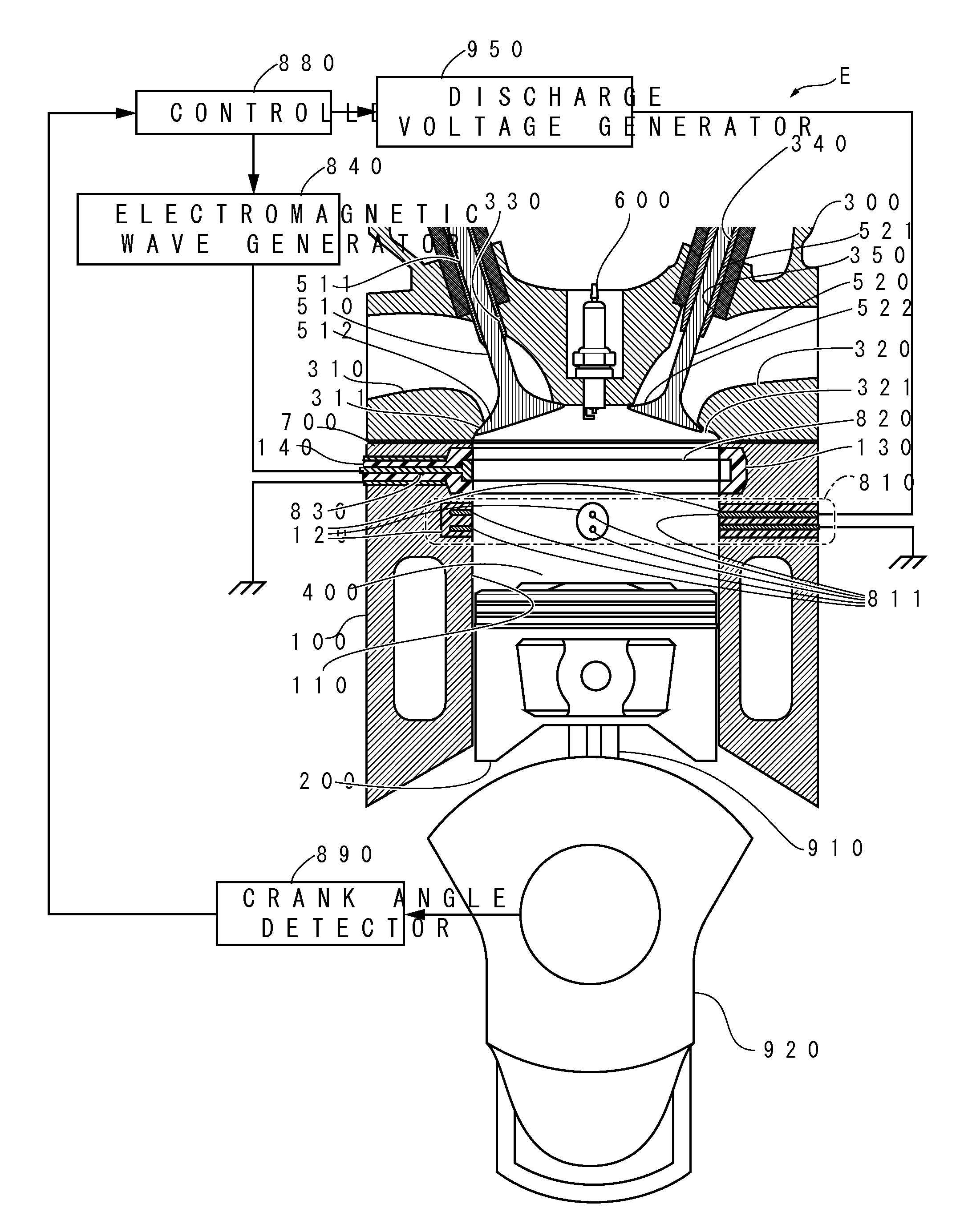
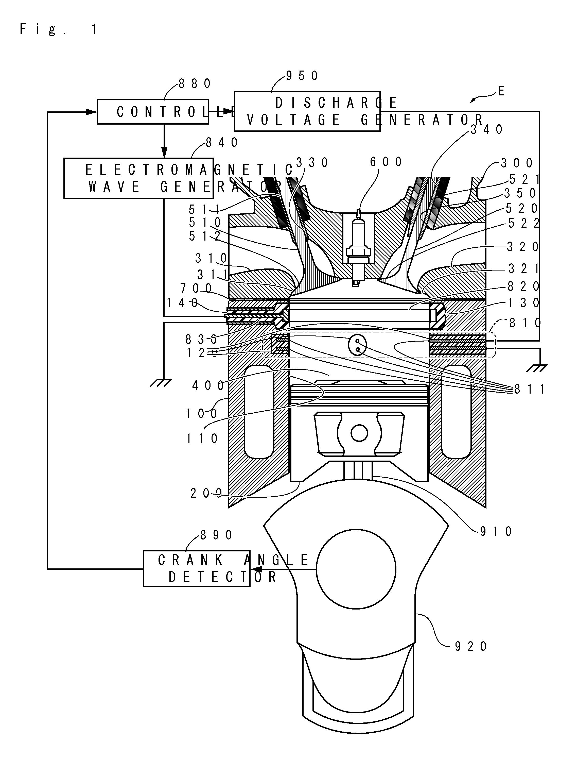
[0081]The after-treatment apparatus for exhaust gas in a combustion chamber of the present invention may be configured such that discharge is generated with the electrode of the discharge device and the electromagnetic waves fed from the electromagnetic wave generator through the electromagnetic wave transmission line are radiated from the antenna, while the exhaust gas remains in the combustion chamber after the exhaust gas is produced during the explosion stroke. Control method shown in FIG. 5 and explained is one example. Even though there are various embodiments, the after-treatment apparatus for exhaust gas in a combustion chamber of the first embodiment is configured such that discharge is generated with the electrode 811 of the discharge device 810 and the electromagnetic waves fed from the electromagnetic wave generator 840 through the electromagnetic wave transmission line 830 are radiated from an antenna 820, from the time when exhaust gas is produced at the explosion stro...

second embodiment

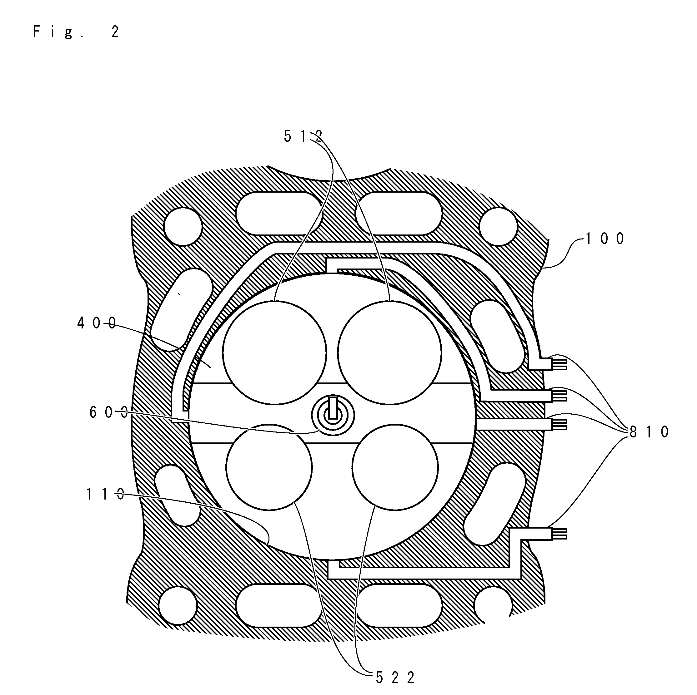
[0085]Hereinafter, the after-treatment apparatus for exhaust gas in a combustion chamber in second embodiment will be described. FIG. 6 shows the embodiment of the internal combustion engine E with the gasket 700. The present invention targets reciprocating engines. In this embodiment, engine E is a four-cycle gasoline engine. Item 100 is the cylinder block. Cylinder block 100 contains cylinder 110, which has an approximately circular cross section. Cylinder 110 penetrates cylinder block 100. Piston 200, which has an approximately circular cross section corresponding to cylinder 110, fits into cylinder 110 and reciprocates freely. Cylinder head 300 is assembled on the anti-crankcase side of cylinder block 110. Cylinder head 300, piston 200, and cylinder 110 form combustion chamber 400. Item 910 is a connecting rod, with one end connected to piston 200 and the other end connected to crankshaft 920, which is the output shaft. Cylinder head 300 has intake port 310, which is a component...

third embodiment

[0108]Hereinafter, the after-treatment apparatus for exhaust gas in a combustion chamber in third embodiment will be described. FIG. 16 shows the embodiment of the internal combustion engine E. The present invention targets reciprocating engines. In this embodiment, engine E is a four-cycle gasoline engine. Cylinder block 100 contains cylinder 110, which has an approximately circular cross section. Cylinder 110 penetrates cylinder block 100. Piston 200, which has an approximately circular cross section corresponding to cylinder 110, fits into cylinder 110 and reciprocates freely. Cylinder head 300 is assembled on the anti-crankcase side of cylinder block 110. Cylinder head 300, piston 200, and cylinder 110 form combustion chamber 400. Item 910 is a connecting rod, with one end connected to piston 200 and the other end connected to crankshaft 920, which is the output shaft. Cylinder head 300 has intake port 310, which is a component of the intake line, and exhaust port 320, which is ...


PUM


Abstract

An after-treatment apparatus for exhaust gas in a combustion chamber includes a discharge device with an electrode exposed to the combustion chamber and installed in at least one of members constituting the combustion chamber, an antenna installed in at least one of the members constituting the combustion chamber so as to radiate electromagnetic waves into the combustion chamber, an electromagnetic wave transmission line installed in at least one of the members constituting the combustion chamber and with one end connected to the antenna and the other end covered with an insulator or dielectric and extending to a portion, in at least one of the members constituting the combustion chamber, distant from the combustion chamber, and an electromagnetic wave generator for feeding electromagnetic waves to the electromagnetic wave transmission line. The after-treatment apparatus is configured such that discharge is generated with the electrode of the discharge device and the electromagnetic waves fed from the electromagnetic wave generator through the electromagnetic wave transmission line are radiated from the antenna, while the exhaust gas remains in the combustion chamber after the exhaust gas is produced during the explosion stroke.

Description

TECHNICAL FIELD[0001]This invention belongs to the technical field of the internal combustion engine and relates to an after-treatment apparatus for exhaust gas in an internal combustion engine with an intake-exhaust system.BACKGROUND OF THE INVENTION[0002]The gas in an internal combustion engine contains gas state components, PM (Particulate Matter, can say Particulate), unburned hydrocarbons (UBS or HC), carbon monoxide (CO), nitric oxides (NOX), carbon dioxide (CO2), water vapor (H2O), oxygen (O2), and nitrogen (N2) and so on. PM in exhaust gas from, for example diesel among internal combustion engines, points solid or liquid particles larger than 10 μm. The solid or liquid particles include soot consisting of carbonaceous, combustible organic fraction that consists high-boiling-point carbon hydride and sulfate moieties.[0003]For example, Patent Document 1 discloses a discharge type exhaust gas control apparatus that includes a diesel particulate filter and a plasma generator as ...

Claims


Application Information

Patent Timeline
Patent Type & Authority Applications(United States)
IPC IPC(8): F01N3/01
CPCF01N3/0892F02P23/045F01N2240/28F02P15/02F01N3/02F01N3/08F02P15/08
Inventor IKEDA, YUJI
Owner MAGINEERING INC
Why Eureka
Try Eureka