Abnormality diagnosis device of internal combustion engine

a technology of abnormality diagnosis and internal combustion engine, which is applied in the direction of combustion-air/fuel-air treatment, electric control, instruments, etc., can solve the problems that the combustion processing of blow-by gas cannot be properly performed, and achieve the effects of improving diagnostic accuracy, high sensing accuracy, and better respons

Active Publication Date: 2011-02-03
DENSO CORP
View PDF6 Cites 40 Cited by
  • Summary
  • Abstract
  • Description
  • Claims
  • Application Information

AI Technical Summary

Benefits of technology

[0020]According to a sixth example aspect of the present invention taking this point into account, the flow sensor is a thermal type sensor that has a heating section and a temperature sensing section provided on a semiconductor substrate. The flow sensor according to the above-descr

Problems solved by technology

In such the case, there is a possibility that combustion p

Method used


Image

  • Abnormality diagnosis device of internal combustion engine
  • Abnormality diagnosis device of internal combustion engine
  • Abnormality diagnosis device of internal combustion engine

Examples


first embodiment

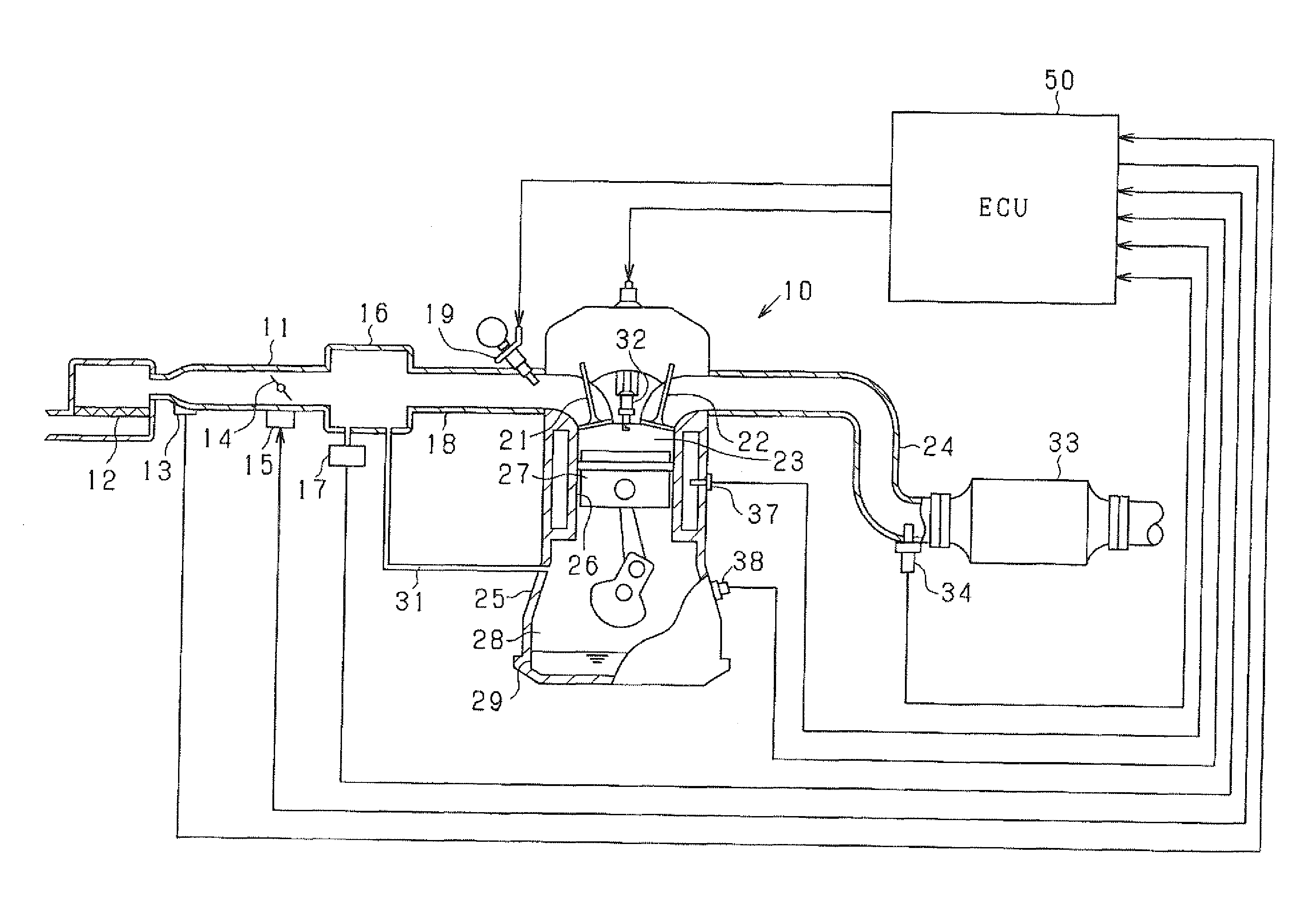
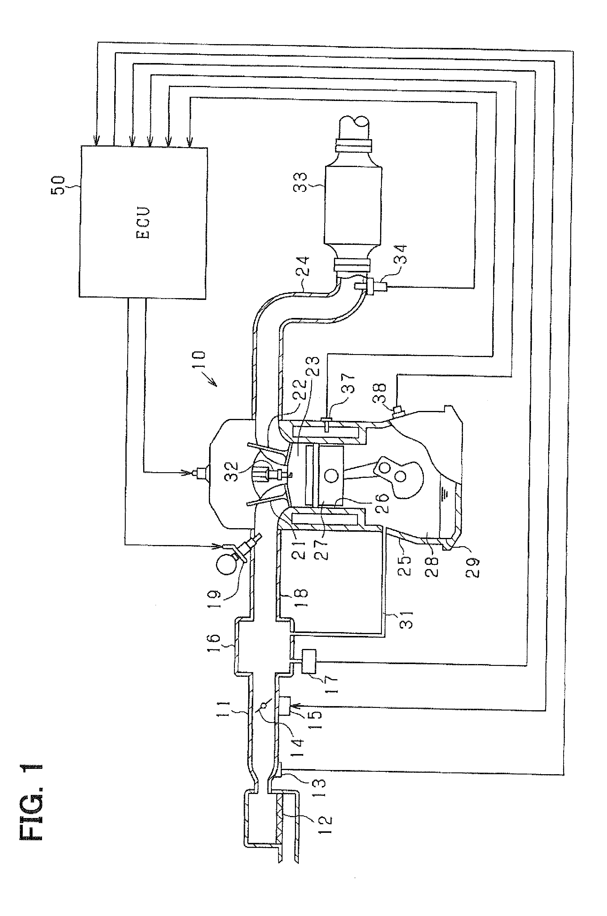
[0027]Hereafter, a first embodiment of the present invention will be described with reference to the drawings. The present embodiment is constructed as an engine control system for an in-vehicle multi-cylinder gasoline engine (internal combustion engine). The control system performs control of a fuel injection quantity, control of ignition timing and the like centering on an electronic control unit (referred to as ECU, hereinafter). FIG. 1 is a schematic construction diagram schematically showing the entire engine control system.

[0028]In the engine 10 shown in FIG. 1, an air cleaner 12 is provided in the most upstream portion of an intake pipe 11 (intake passage). An air flow meter 13 for sensing an intake air quantity is provided downstream of the air cleaner 12.

[0029]In the present embodiment, a thermal type flow sensor is adopted as the air flow meter 13. The air flow meter 13 has a semiconductor substrate, on which a heating resistor and a temperature sensing resistor are provid...

second embodiment

[0056]Next, a second embodiment of the present invention will be described, focusing on differences from the first embodiment. In the above-described first embodiment, the clogging abnormality of the PCV passage 31 is diagnosed based on the pulsation width of the intake air flow rate. In the second embodiment, a clogging abnormality in the EGR passage is diagnosed based on the pulsation width of the intake air flow rate in addition to the diagnosis of the PCV passage. The EGR passage is a branch passage that branches from the intake pipe and that is different from the PCV passage.

[0057]The system configuration of the present embodiment is different from the first embodiment mainly in that the exhaust pipe 24 upstream of the three-way catalyst 33 is connected to the intake system (surge tank 16 in present embodiment) via an EGR passage 35 as shown in FIG. 4. Alternatively, the EGR passage 35 may be connected to the exhaust system downstream of the three-way catalyst 33.

[0058]An elect...


PUM


Abstract

An engine has a PCV passage connected to an intake system for recirculating a blow-by gas to the intake system and an air flow meter provided upstream of a connection between the PCV passage and the intake system in the intake system for sensing an intake air flow rate. An electronic control unit (ECU) performing various types of control of the engine diagnoses a clogging abnormality of the PCV passage based on pulsation width of the intake air flow rate sensed with the air flow meter. A thermal type sensor having a heating section and a temperature sensing section provided on a semiconductor substrate is used as the air flow meter.

Description

CROSS REFERENCE TO RELATED APPLICATION[0001]This application is based on and incorporates herein by reference Japanese Patent Application No. 2009-176051 filed on Jul. 29, 2009.BACKGROUND OF THE INVENTION[0002]1. Field of the Invention[0003]The present invention relates to an abnormality diagnosis device of an internal combustion engine for diagnosing a clogging abnormality of a PCV passage (positive crankcase ventilation passage) recirculating a blow-by gas to an intake system.[0004]2. Description of Related Art[0005]Conventionally, there have been proposed various devices for diagnosing an abnormality related to a PCV passage (for example, refer to Patent document 1: JP-A-2007-2838). According to Patent document 1, an air quantity upstream of a connection between an intake system and the PCV passage in an intake passage is sensed with an air flow meter. The abnormality in the PCV passage is diagnosed based on a result of comparison between the sensed air quantity and a determinati...

Claims


Application Information

Patent Timeline
IPC IPC(8): F02B25/06G01M15/04
CPCF01M13/00F02D41/18Y02T10/121F02M25/06F02M35/10222F02D41/22Y02T10/12
Inventor YAMASHITA, HIROSHI
Owner DENSO CORP
Why Eureka
Try Eureka