Nondestructive analysis for periodic structure

a periodic structure, non-destructive technology, applied in the direction of instruments, photomechanical devices, optics, etc., can solve the problems of difficult to perform an accurate analysis using a pattern tester, excessively long time to obtain the result of the measurement, and inability to use fabricated semiconductor devices, etc., to achieve accurate calculation of the physical properties related to the reflectance or transmittance, the effect of more rapid performan

Inactive Publication Date: 2011-02-03
UNIV IND COOP GRP OF KYUNG HEE UNIV
View PDF1 Cites 2 Cited by
  • Summary
  • Abstract
  • Description
  • Claims
  • Application Information

AI Technical Summary

Benefits of technology

[0021]Accordingly, in accordance with a particular embodiment of the present invention, by discretizing the Lippmann-Schwinger equation using M-th order interpolation, an accurate calculation of the physical properties related to the reflectance or transmittance of the virtual periodic structure can be performed more rapidly. Furthermore, microscopic change relative to an original periodic structure having a native oxide layer thereon or an intentionally formed surface coating layer thereon can be precisely tested. The development of the semiconductor industry or other nano-technology can benefit from such embodiment of the invention.

Problems solved by technology
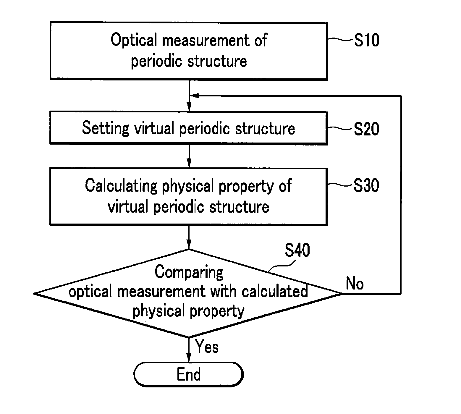
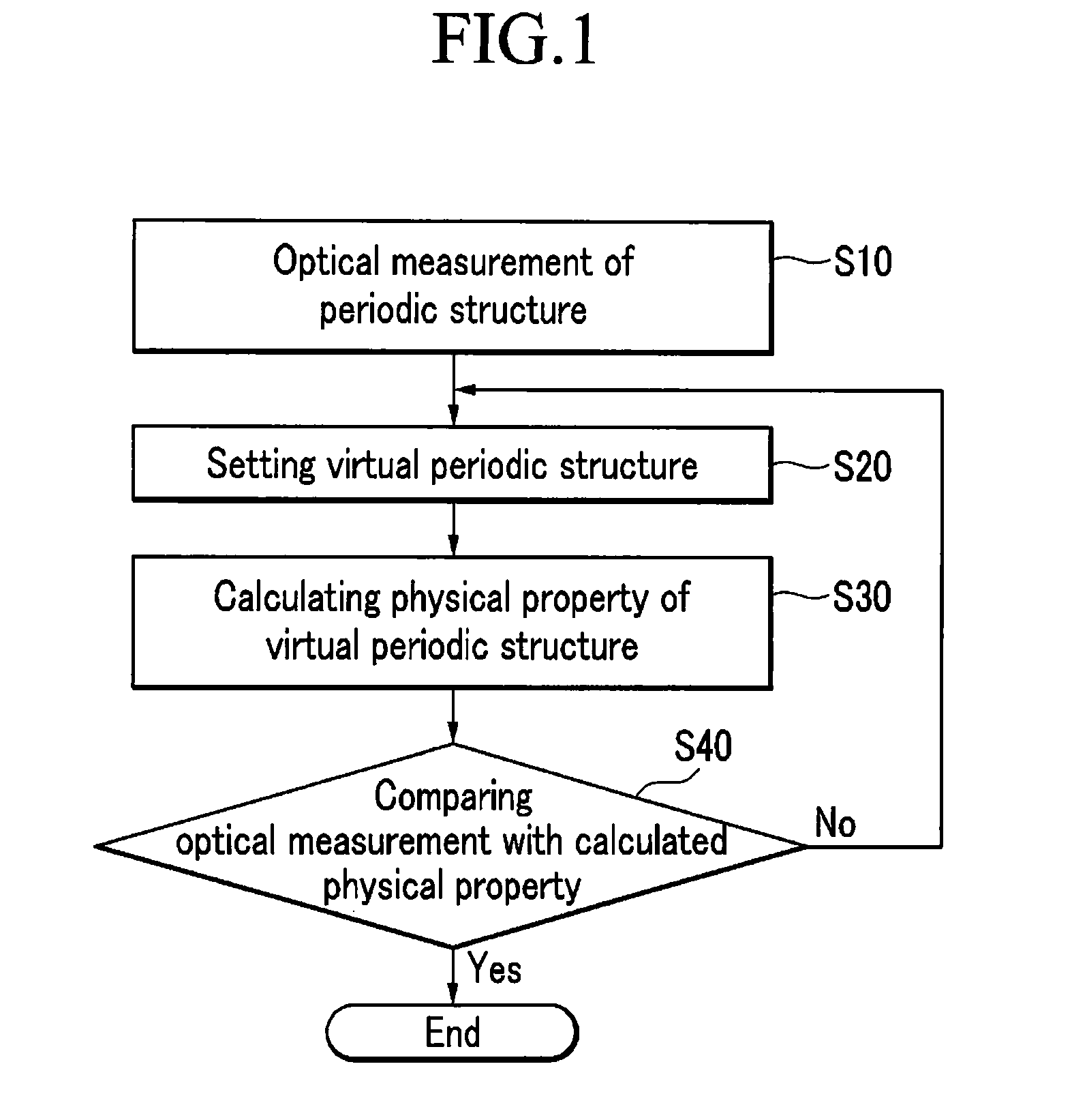
However, since the resolution of the pattern tester can be insufficient for determining the shapes of “nano-level” patterns that measure only a few nanometers in length, it is difficult to perform an accurate analysis using a pattern tester.
However, when an electron microscope is used, since a section of a semiconductor device is cut for shape analysis thereof, the fabricated semiconductor device cannot be used again.
Moreover, since the measurement is conducted under a vacuum environment, it can take an excessively long time to obtain a result of the measurement.
It may also be impossible to select various regions of a sample to be measured.
Due to the aforementioned drawbacks, the electron microscope has a limit in its practical use in the production line.
A calculation method using EMA has a problem in that, since an approximation is obtained by only a volume ratio of constituent substances in a given period, regardless of a detailed shape of a structure, it never distinguishes a detailed shape of the structure.
Specifically, in the periodic structure, since the calculation method using the EMA cannot clarify the different periodic structures if their volume ratios are the same, a new optical measurement method is particularly needed.

Method used


Image

  • Nondestructive analysis for periodic structure
  • Nondestructive analysis for periodic structure
  • Nondestructive analysis for periodic structure

Examples


embodiment

[0067]Among the intermediate steps for calculating the reflectance or transmittance of the virtual periodic structure (200b) illustrated in FIGS. 6 and 7, two steps, one for discretizing the Lippmann-Schwinger equation by use of the second-order interpolation and the other for creating a system of linear equations for the discretized projected-space perturbed waves, will be described below.

[0068]Below, the calculation will be carried out separately for TE and TM modes. The TE mode case is considered first.

[0069]Due to the periodicity of any periodic structure in the x direction, the x-dependence of the TE mode components are completely determined in Fourier-Floquet series:

Ey(x,z)=∑n=-∞∞Ψn(z)kxnx,Eq.(1)Hx(x,z)=ɛ0μ01k0∑n=-∞∞∂zΨn(z)kxnx,Eq.(2)

where i=√{square root over (−1)}; kxn=k0[nl sin θ−nλ0 / Λ]; k0=2π / λ0 (with λ0 being the wavelength of an incident wave in vacuum, nl being the refractive index of an incident region, and θ being the incident angle); ε0 is the permittivity of the vac...


PUM

PropertyMeasurementUnit
reflectivityaaaaaaaaaa
transmittanceaaaaaaaaaa
periodic structureaaaaaaaaaa

Abstract

There is provided a nondestructive analysis for a periodic structure. In the method, a virtual periodic structure is set and divided into a plurality of layers. By utilizing the Lippmann-Schwinger equation with an M-th order interpolation, physical properties related to reflectivity or transmittance of the virtual periodic structure are calculated. An M-th order interpolation formula employed in discretization of the Lippmann-Schwinger equation leads to an accurate and rapid calculation of the physical properties of the periodic structure.

Description

CROSS-REFERENCE TO RELATED APPLICATIONS[0001]This application claims priority and the benefit of Korean Patent Applications No. 10-2009-0070308 filed on Jul. 30, 2009 and No. 10-2010-0009753 filed on Feb. 2, 2010 in the Korean Intellectual Property Office, the entire contents of which are incorporated herein by reference.BACKGROUND OF THE INVENTION[0002]1. Technical Field[0003]The present invention described herein relates to an analysis method for a periodic structure, the method exemplarily performed through non-destructive testing via measurement of reflectance or transmittance.[0004]2. Discussion of Related Art[0005]Generally, to fabricate electronic devices such as semiconductor devices or display devices, processes of cleaning, thin-film growing, photolithography, and thin-film etching are repeated many times to produce consumer products. For example, in the photolithography process, a circuit of a mask where an image to be fabricated is formed and is transferred to a photosen...

Claims


Application Information

Patent Timeline
Patent Type & Authority Applications(United States)
IPC IPC(8): G06F15/00G01N21/55G01N21/59G01B11/02G01B11/24G01N21/47G01N21/956
CPCG01N21/8422G03F7/70625G01N21/95607
Inventor KIM, YOUNG DONGCHUNG, JIN-MOHAN, SEUNG-HO
Owner UNIV IND COOP GRP OF KYUNG HEE UNIV
Why Eureka
Try Eureka