Pulsed optical source

a pulsed optical source and source technology, applied in the field of pulsed optical radiation sources, can solve the problems of affecting both the spectrum and the noise level of the seed source, unable to easily vary in the field without compromising laser performance, and unable to achieve the effect of preventing back reflection

Active Publication Date: 2011-02-10
LUMENTUM OPERATIONS LLC
View PDF13 Cites 38 Cited by
  • Summary
  • Abstract
  • Description
  • Claims
  • Application Information

AI Technical Summary

Benefits of technology

[0008]In accordance with the invention, there is provided an optical pulse source, which comprises a seed optical source for providing seed optical radiation, a pulsed optical amplifier (POA) coupled to the seed optical source for amplifying the seed optical radiation in dependence upon an electrical pulse signal applied thereto, and for producing a pulsed optical signal comprising optical pulses of a pulse duration defined by the electrical pulse signal, an optically isolating device disposed in an optical path between the seed optical source and the POA for preventing back reflections into the seed optical source, and an output optical port for outputting the pulsed optical signal. The optical pulse source further includes a POA controller for providing the electrical pulse signal to the pulsed optical amplifier. The pulsed optical signal at the output port has an optical spectral shape that is defined substantially by the seed optical source, and has a temporal pulse shape that is defined substantially by the POA controller.

Problems solved by technology

Such lasers typically rely on Q-switching and / or mode locking to generate optical pulses and therefore produce optical pulses with characteristics that are predetermined by the cavity geometry, mirror reflectivities, and the like, and cannot generally be easily varied in the field without compromising the laser performance.
Such lasers, however, typically require a seed pulse source for providing, or “seeding” the fiber amplifier with seed optical pulses.
Directly pulsing the laser diode current can however generate transient effects that can disadvantageously affect both the spectrum and the noise level of the seed source.
In the case of Fabry-Perot (FP) laser diodes, longitudinal mode beating can lead to high frequency noise which consequently gives rise to peak power fluctuations in the pulse structure, which is a disadvantage.
The frequency chirping of the modulated DFB laser does not broaden the linewidth sufficiently to suppress SBS, limiting the use of DFB lasers to pulse duration of less than about 2 ns.
In principle, the laser drive current could be modulated to broaden the linewidth, but this approach would significantly complicate the laser drive electronics.
Additionally, the DFB and DBR lasers can exhibit mode hopping behaviors under some pulsed drive conditions that may cause undesirable complications in applications that rely on stable-single-frequency output.
Disadvantages of such designs include their relatively high cost and complexity requiring three or more active components, a relatively high noise level compared to semiconductor amplifiers, and drawbacks in performance related to the use of conventional optical modulators, including bias-point drift, limited contrast ratio, and photorefractive damage.

Method used


Image

  • Pulsed optical source
  • Pulsed optical source
  • Pulsed optical source

Examples


Embodiment Construction

[0026]In the following description, the term “light” is used to refer to electromagnetic radiation, including but not limited to visible light. Furthermore, the term “optical” is used to qualify all electromagnetic radiation, including light in the visible spectrum and light in other wavelength ranges. The terms “optical radiation”, “optical signal”, and “light” are used herein interchangeably and encompass visible light and non-visible light such as ultraviolet (UV) light and infrared (IR) light.

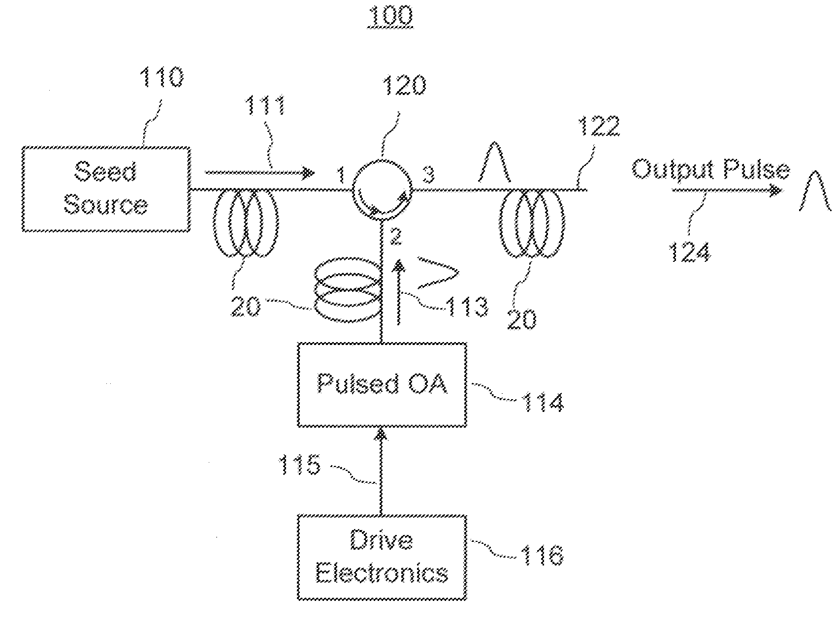
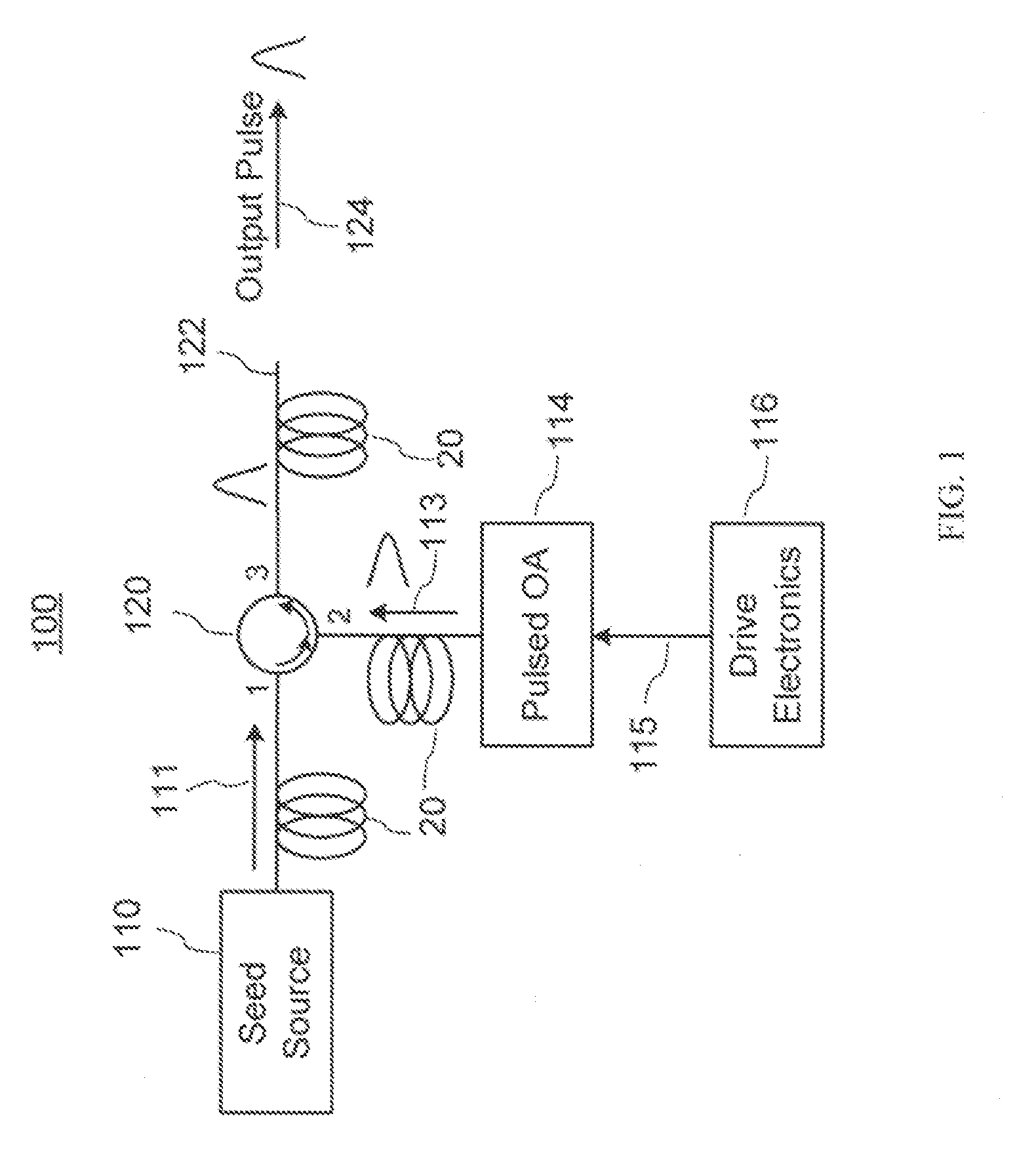
[0027]Exemplary embodiments of an optical pulse source (OPS) according to the present invention are shown in FIGS. 1, 5-10, and are hereafter described.

[0028]With reference to FIG. 1, an OPS 100 includes a seed optical source (SOS) 110 for providing seed optical radiation 111, a pulsed optical amplifier (POA) 114 which is optically coupled to the SOS 110 to receive the seed optical radiation 111 for pulsed amplification thereof, and an output optical port 122 which is in turn optically coup...


PUM


Abstract

The invention relates to pulsed optical sources formed of a source of seed optical radiation, a pulsed optical amplifier for pulsing the seed optical radiation, and an output optical port for outputting a pulsed optical signal produced by the pulsed optical amplifier. An optically isolating element such as an optical circulator is provided in the optical path between the optical seed source and the pulsed optical amplifier.

Description

CROSS-REFERENCE TO RELATED APPLICATIONS[0001]The present invention claims priority from U.S. Provisional Patent Application No. 61 / 231,288 filed Aug. 4, 2009, entitled “Versatile Pulsed Source for Optical Amplification”, which is incorporated herein by reference for all purposes.TECHNICAL FIELD[0002]The present invention generally relates to sources of pulsed optical radiation, a more particularly relates to sources of optical pulses incorporating pulsed optical amplifiers.BACKGROUND OF THE INVENTION[0003]Pulsed laser sources are used in a variety of applications, including material processing, optical communications and measurements. Diode-pumped solid-state lasers, for example Nd:YAG lasers, have been conventionally used in applications requiring high peak optical power, such as marking, engraving, micro-machining, cutting, and other material-processing applications. Such lasers typically rely on Q-switching and / or mode locking to generate optical pulses and therefore produce opti...

Claims


Application Information

Patent Timeline
Patent Type & Authority Applications(United States)
IPC IPC(8): H01S5/50
CPCH01S3/06754H01S3/11H01S2301/02H01S3/2333H01S5/50H01S3/1618H01S3/0085H01S3/0078H01S3/2375H01S3/06795H01S5/06216
Inventor KLINER, DAHVMUENDEL, MARTIN H.EYRES, LOREN
Owner LUMENTUM OPERATIONS LLC
Why Eureka
Try Eureka