
Method and system for removing h2s from a natural gas stream

Active Publication Date: 2011-02-17
TWISTER BV
View PDF7 Cites 22 Cited by
  • Summary
  • Abstract
  • Description
  • Claims
  • Application Information

AI Technical Summary

Benefits of technology

[0004]Recently process schemes have been developed to effectively pre-treat natural gas streams at low temperature in order to recover and fractionate the low boiling vapours such as C2, C3, C4 and also H2S and CO2. One of these low temperature schemes is published in International patent application WO2006 / 089948. This prior art reference discloses the use of a cyclonic separator to optimize the thermodynamic performance whilst reducing the size of costly fractionation columns and reflux chillers compared to the traditional low temperature schemes. One of the teachings in this patent publication is that it is thermodynamically more favourable to cool the inlet stream to the cyclonic separator with a chiller than it is to cool the liquid enriched secondary outlet stream of the cyclonic separator with a chiller.
[0005]Fractionation columns are well known in the industry. Recently Total (TFE) and Institute Français du Petrole (IFP), have developed an improved fractionation process for low temperature H2S removal process is the so called SPREX process. This SPREX scheme is operating a fractionation column fed with pre-cooled gas at a feed temperature of 25-30° C. The overhead gas—containing predominantly methane and H2S—is cooled down to approx −30° C. with a chilling device. The liquid condensing in the chiller, which predominantly consists of H2S, is fed back to the top tray of the column as reflux. This H2S reflux dissolves the majority of the water entering the column. By using this H2S reflux as desiccant, hydrates can be avoided even when the column top temperature of the fluid is operated at −5° C. at a pressure of ˜80 bar. The H2S enriched liquid stream leaving the bottom of the column is thereafter pumped into the gas reservoir, thereby avoiding costly, large scale amine absorption towers and Claus process as well as avoiding operational costs associated with the disposal of huge amounts of elementary sulphur.
[0007]The method according to the present invention aims to provide a pre-treatment process using a cyclonic separator upstream of a fractionation column, thereby reducing the gas load on the column and meanwhile achieving a lower temperature in the top of the column thereby enhancing H2S recovery and / or the cooling efficiency.SUMMARY OF THE INVENTION

Problems solved by technology

Especially for H2S rich gas fields (10-90 mole % H2S) Amine plants followed by a Claus process become uneconomical.
Unfortunately, the incremental investment saving of the smaller Amine+Claus plant do not outweigh the incremental cost of these increasingly larger chillers.

Method used


Image

  • Method and system for removing h2s from a natural gas stream
  • Method and system for removing h2s from a natural gas stream
  • Method and system for removing h2s from a natural gas stream

Examples


first embodiment

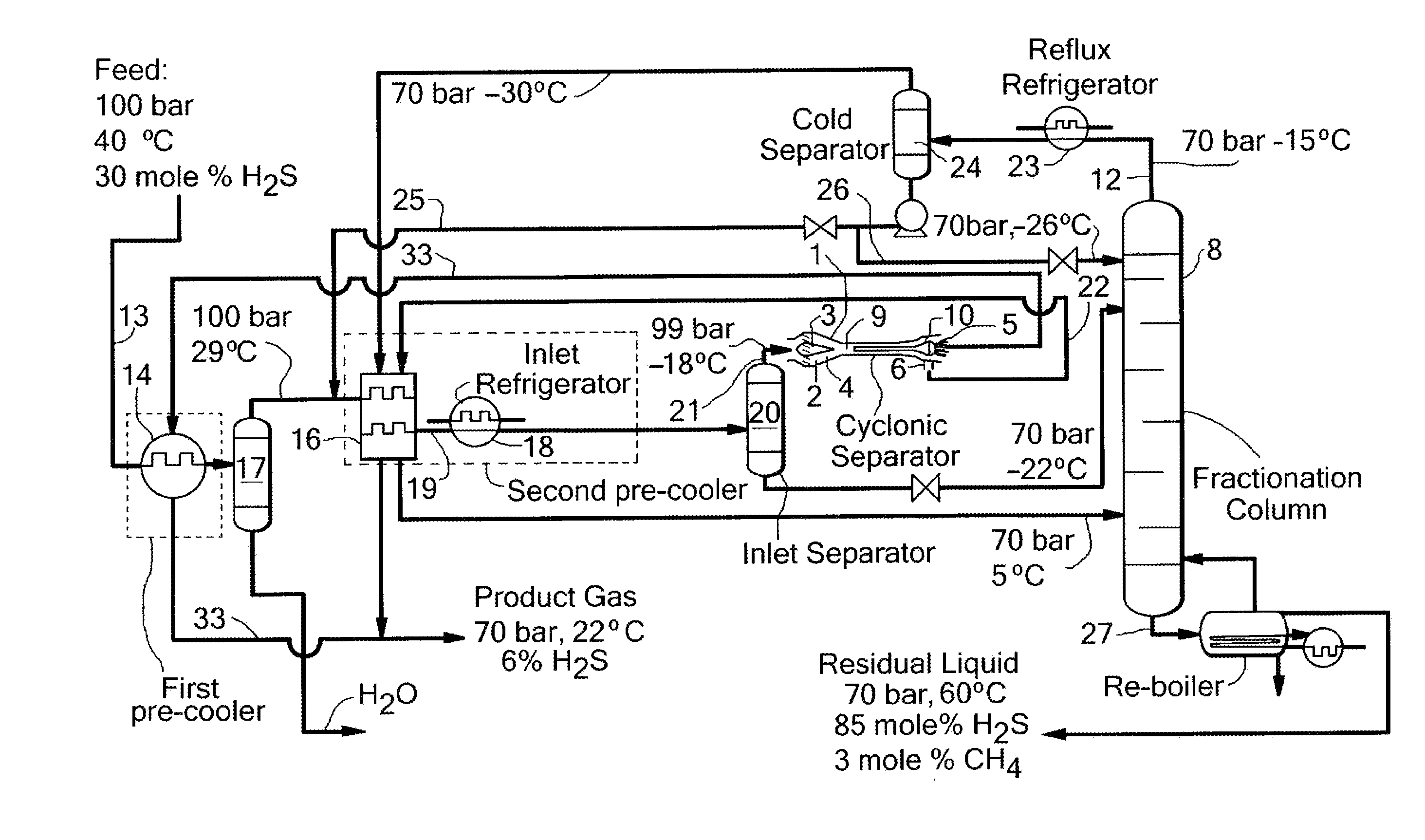
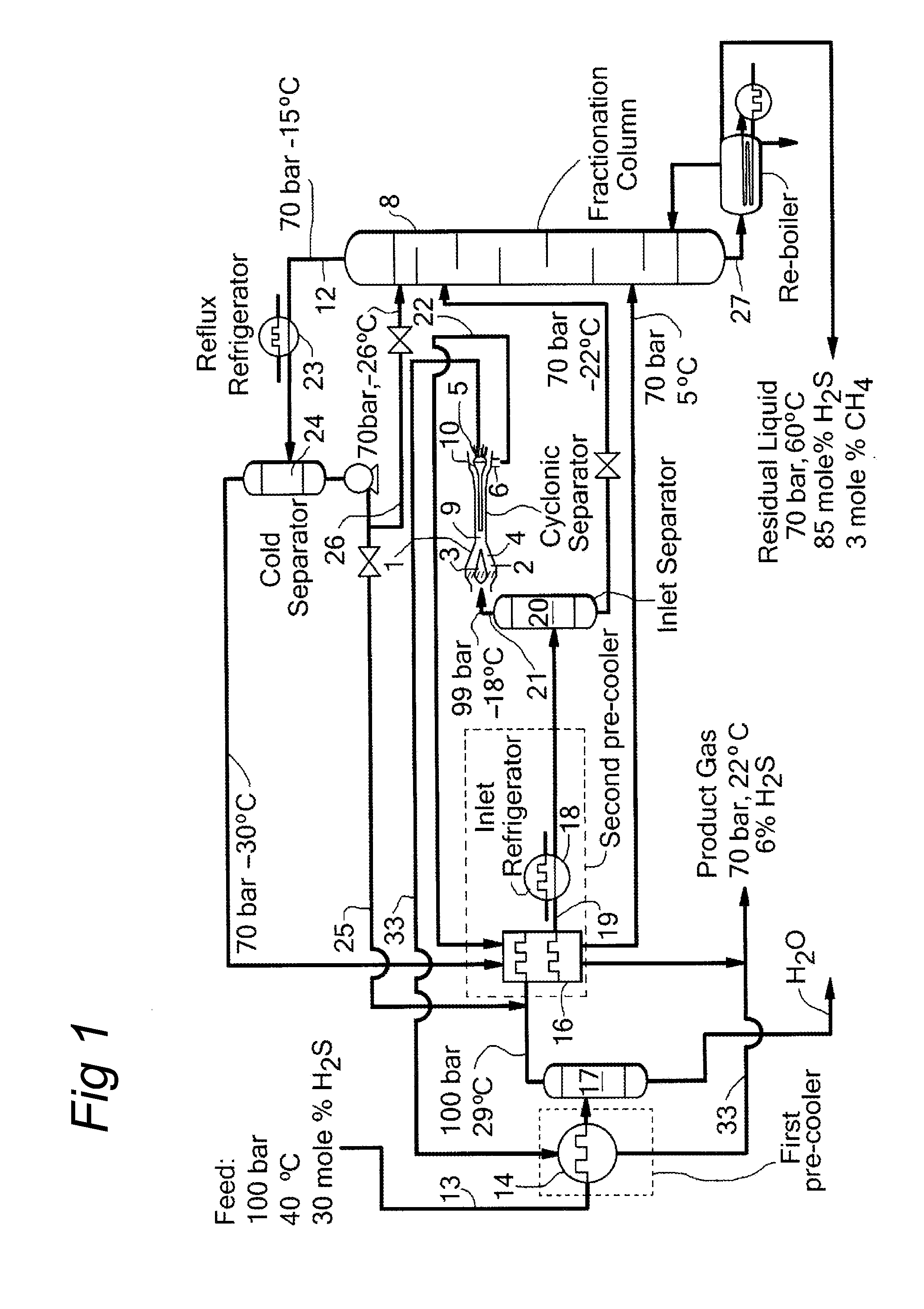
[0035]FIG. 1. shows a flow scheme of the method according to the present invention in which a H2S rich feed (typically H2S=30 mole %) natural gas stream 13 flows through a feed conduit in which the natural gas stream is pre cooled in a first heat exchanger 14 by the cooled H2S lean product gas leaving the central outlet 5 of the cyclonic separator 1 (1st pre-cool step) and subsequently in a second heat exchanger 16 with the H2S lean product gas discharged by the upper outlet conduit 12 at the top of the fractionating column 8 (2nd pre-cool step). After the first pre-cool step free hydrocarbon liquid and water are removed with a bulk water separator 17. This first heat exchanger 14 reduces the fluid temperature of the natural gas stream to well above the hydrate formation temperature (˜29° C. at 100 bar). Upstream of the second heat exchanger 16, liquefied H2S is injected via a first reflux conduit 25 of which a part may evaporate. The remaining H2S liquid will absorb the major part ...

second embodiment

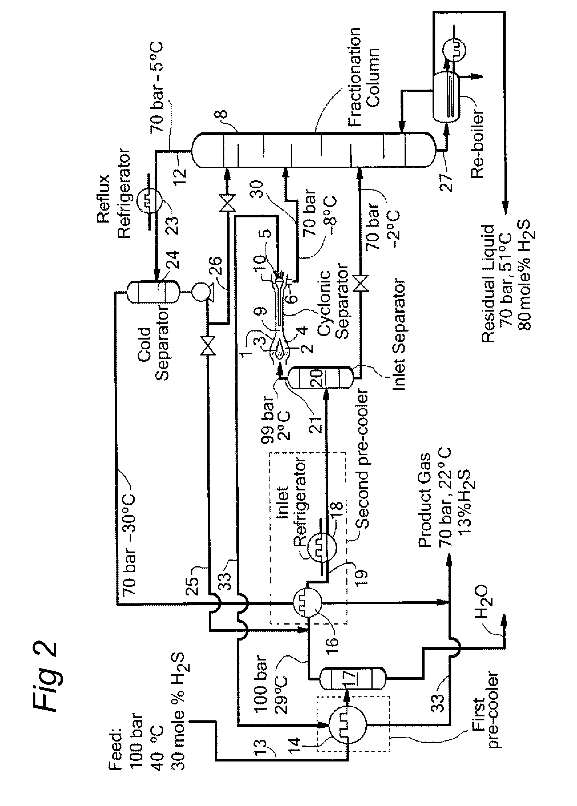
[0043]FIG. 2 depicts a flow scheme of the method according to the invention, which is largely similar to the flow scheme shown in FIG. 1 and in which similar components are identified by similar reference numerals, but wherein the H2S enriched fluid fraction discharged from the outer outlet 6 of the cyclonic separator 1 is discharged by a conduit 30 directly into the fractionating column 8.

third embodiment

[0044]FIG. 3 depicts a flow scheme of the method according to the invention, which is largely similar to the flow scheme shown in FIG. 2 and in which similar components are identified by similar reference numerals, but wherein the first reflux conduit 251 is connected in the feed conduit 19 between the outlet of the second heat exchanger 16 and the inlet of the refrigerator 18.

[0045]Advantageously, a first H2S reflux from conduit 251 from the cold top of the fractionation column 8 is returned to the cooled feed stream from the second heat exchanger 16. This first H2S reflux which is relatively dry and relatively cold can be used beneficially for water absorption in the cold part of the feed gas.

[0046]Additionally, a reflux conduit 40 is arranged as conduit between the reboiler and the inlet of the second heat exchanger 16 for introduction of bottom product of a liquid H2S stream 27 that is collected in the reboiler, into the feed inlet at ˜29° C.

[0047]Advantageously, the bottom prod...


PUM


Abstract

A method for removing hydrogen sulphide (H2S) from a natural gas stream comprising methane (CH4) and H2S comprises:—cooling the natural gas stream in a heat exchanger assembly (13,16,18);—feeding at least part of the cooled natural gas stream through a feed conduit (19,21) into a cyclonic expansion and separation device (1) in which the cooled natural gas stream is expanded in a nozzle (4) and thereby further cooled to a temperature and pressure below the dew point of H2S and is separated by inducing the cooled natural gas stream to swirl in a tubular separation chamber (9) thereby inducing centrifugal forces to separate the cooled natural gas stream into a cooled low density fluid fraction, which is H2S depleted and methane enriched, and a cooled high density fluid fraction, which is H2S enriched and methane depleted;—feeding the cooled low density fluid fraction to a product gas conduit (33) which is connected to the heat exchanger assembly (14) for cooling the natural gas stream fed to the cyclonic expansion and separation device (1); and—feeding the cooled high density fluid fraction to a fractionating column (8) for further separation.

Description

[0001]The invention relates to a method for removing hydrogen sulphide from a natural gas stream.[0002]Highly sour natural gas streams may contain more than 10 mole % Hydrogen Sulphide (H2S).[0003]Sour natural gas streams are often treated in amine plants with Amine absorption columns. The regenerated gas stream from the amine plant is released at fairly low pressure and needs further treatment using a Claus process to transform the H2S in to elementary sulphur. Especially for H2S rich gas fields (10-90 mole % H2S) Amine plants followed by a Claus process become uneconomical.[0004]Recently process schemes have been developed to effectively pre-treat natural gas streams at low temperature in order to recover and fractionate the low boiling vapours such as C2, C3, C4 and also H2S and CO2. One of these low temperature schemes is published in International patent application WO2006 / 089948. This prior art reference discloses the use of a cyclonic separator to optimize the thermodynamic p...

Claims


Application Information

Patent Timeline
IPC IPC(8): F25J3/00
CPCB01D53/24B01D2257/304C10L3/102C10L3/10B01D2258/06F25J3/0209F25J2205/10F25J2200/70F25J3/0233B01D53/52C10L3/103
Inventor BETTING, MARCOTJEENK WILLINK, CORNELIS ANTONIEVAN BAKEL, ROBERT PETRUS
Owner TWISTER BV
Learn More