Low stress soft charge circuit for diode front end variable frequency drive

a diode front end variable frequency drive and low stress technology, applied in the field of soft charge circuits, can solve the problems of high surge current, harmful system start-up transients, and inability to reverse the dc-ac conversion,

a diode front end variable frequency drive and low stress technology, applied in the field of soft charge circuits, can solve the problems of high surge current, harmful system start-up transients, and inability to reverse the dc-ac conversion,

US20110038185A1Inactive Publication Date: 2011-02-17YASKAWA ELECTRIC AMERICA

Image

  • Low stress soft charge circuit for diode front end variable frequency drive
  • Low stress soft charge circuit for diode front end variable frequency drive
  • Low stress soft charge circuit for diode front end variable frequency drive

Examples


Embodiment Construction

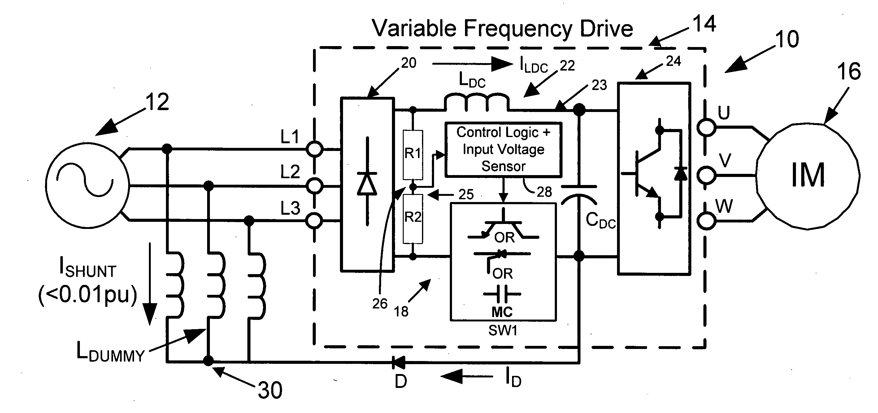
[0034]The present invention uses alternative techniques to soft charge a DC bus capacitor. The technique uses two stage charging and should be able to handle brown out conditions in an efficient manner. The drive unit is both compact and economical. An exemplary topology in accordance with the invention, shown in FIG. 4, generally satisfies these features. The proposed topology includes features similar to a typical star-delta starter used in conventional 3-phase ac motors. The dc bus capacitor is charged as a “semiconverter” at startup. Once the dc bus voltage reaches the steady state voltage dictated by the semiconverter, the full converter configuration is engaged, resulting in a second charge up period. Since the charging is carried out in two stages, the inrush current through the inductor, capacitor, and diode is well controlled with almost no stress. The switching from the semiconverter configuration to the full bridge configuration can either be dictated by level of dc bus v...


PUM


Abstract

A variable frequency drive comprises a diode rectifier receiving multiphase AC power from a source and converting the AC power to DC power. An inverter receives DC power and converts the DC power to AC power to drive a load. A link circuit is connected between the diode rectifier and the inverter and comprises a DC bus to provide a relatively fixed DC voltage for the inverter. A bus capacitor is across the bus. A soft charge circuit limits inrush current to the bus capacitor. The soft charge circuit comprises an inductor connected between the source and the link circuit and a switch circuit in the link circuit for selectively providing a semiconverter configuration or a full bridge converter configuration to provide two stage charging of the bus capacitor.

Description

CROSS REFERENCE TO RELATED APPLICATIONS[0001]This application claims priority of application Ser. No. 61 / 204,732, filed Jan. 9, 2009.FIELD OF THE INVENTION[0002]The present invention relates to variable frequency drives and, more particularly, to a soft charge circuit including a two stage charging circuit.BACKGROUND OF THE INVENTION[0003]AC to DC rectifiers are widely used to convert AC line electric power to DC power to be used by inverters (for motor, UPS, and other applications), DC / DC converters, and passive loads such as resistors. In any rectifier circuit, the AC line voltages are rectified and ripple of the rectified voltage is filtered using a parallel capacitor and occasionally a series inductor. This results in a fixed, i.e., ripple free, DC voltage.[0004]Without appropriate pre-charge circuitry, the start-up transients can be harmful to the systems. If the AC line and / or the DC link filters do not have sufficient impedance, uncontrolled current of large magnitude will fl...

Claims


Application Information

Patent Timeline
17 Feb 2011
Publication
US20110038185A1
IPC
H02J4/00; H02M7/44
CPC
H02J7/045; H02M5/458; H02M1/36; H02J7/345; H02J7/04; H02J7/007182
Inventors
SWAMY, MAHESH M.; KUME, TSUNEO JOE